Catch element of a contact having a nose-shaped projection

Active Publication Date: 2017-05-11
ROBERT BOSCH GMBH
View PDF13 Cites 3 Cited by
  • Summary
  • Abstract
  • Description
  • Claims
  • Application Information

AI Technical Summary

Benefits of technology

[0022]In one aspect of the present invention, a plug-in connector is provided which includes a contact as well as a contact carrier having a contact cavity for the accommodation of the contact. The catch element is designed to project at least partially into a recess of the contact cavity of the contact carrier by its first and second section in the latched state of the contact, in such a way that the second section of the catch element is able to make contact with a sidewall of the recess when the contact moves counter to the plug-in direction, thereby inhibiting a further movement of the contact out of the contact cavity. In other words, when the contact is pulled out, the catch element strikes the sidewall in the contact cavity, i.e. an undercut in the contact cavity, for instance, and mechanically retains the contact in the contact cavity.
[0023]In the latched position, the catch element is in the first position. The mechanical contact with the sidewall of the contact cavity, for example, may come about only when the contact is moved out of the contact cavity, for instance when pulling on the connected cable. In the normal plugged-in state, there may be a gap between the second section of the catch element and the sidewall due to tolerance-related reasons, among other things.
[0024]In one specific embodiment of the present invention, an elasticity of the material of the projection is lower than an elasticity of a material of the sidewall of the contact cavity, so that when the contact is pulled out of the contact carrier or out of the contact cavity and the catch element is consequently pressed against this sidewall or against the undercut, the projection creates a depression in the sidewall in the undercut, so that the depression inhibits a movement of the second section of the catch element in the direction away from the housing of the contact. For instance, the material of the contact cavity, and thus also of the sidewall, may include plastic and the material of the projection may include a metal, for instance.
[0025]The elasticity may be synonymous with the hardness of the material here. The following relation then applies in this context: a h

Problems solved by technology

Especially in the case of miniaturized contacts, on which high mechanical demands are placed despite a small size and low material thicknesses, it may be difficult to satisfy these contradictory demands.
Particularly in the case of high pullout forces, this force component may become so great that the free end of the catch element slides away from the housing along the sidewall

Method used


Image

  • Catch element of a contact having a nose-shaped projection
  • Catch element of a contact having a nose-shaped projection
  • Catch element of a contact having a nose-shaped projection

Examples


Embodiment Construction

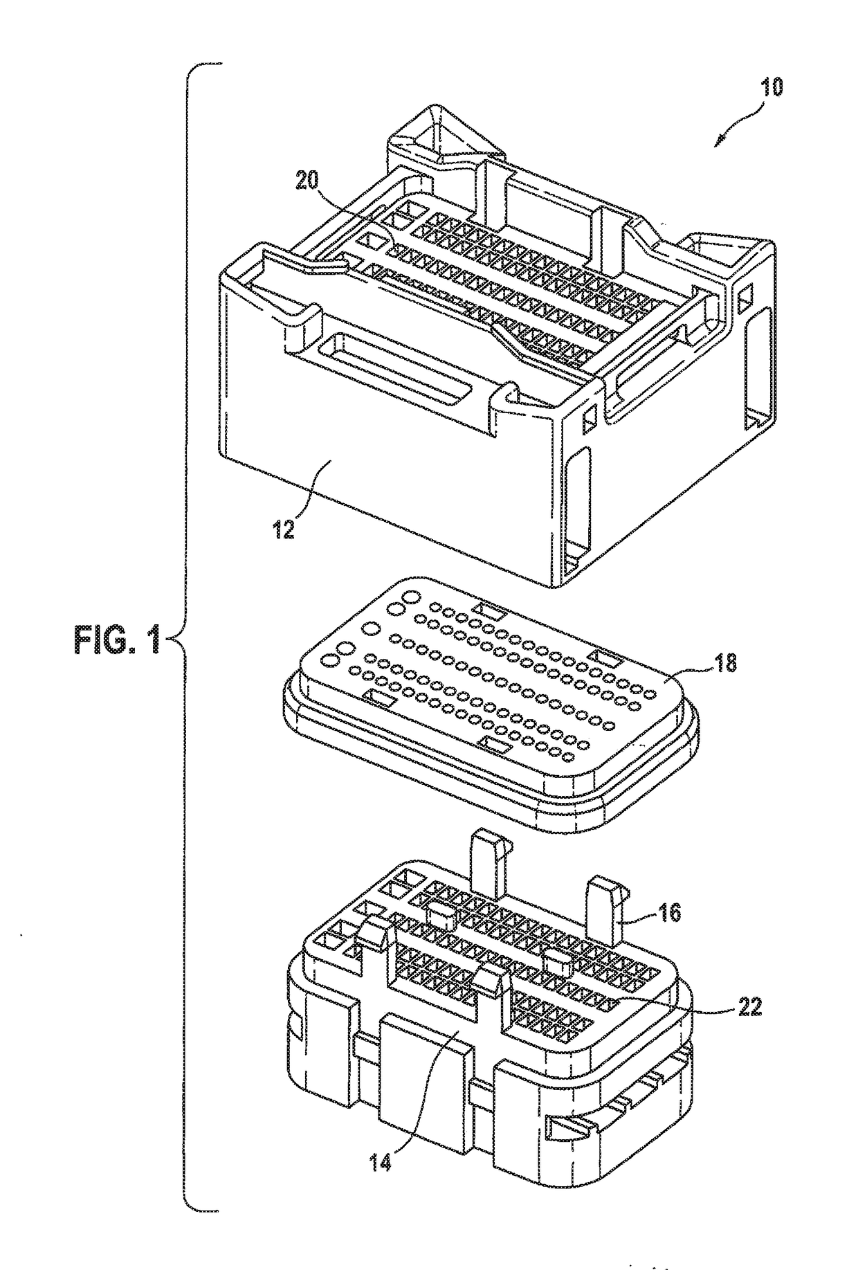
[0036]FIG. 1 shows one example of a plug 10 of a plug-in connector, which may be mechanically and electrically configured for being combined with a corresponding counterplug (not shown). Plug 10, for example, may be used for the mechanical and electrical connection of a plurality of cables to one another or of a cable tree to a control unit in a motor vehicle. Plug 10 has an upper housing part 12 and a lower housing part 14, which are able to be mechanically connected to each other via catch tabs 16. A sealing mat 18 is situated between upper housing part 12 and lower housing part 14. Through-feeds 20 for the mechanical stabilization of the respective electrical line are provided in upper housing part 12, and the associated contact cavities 22 are provided in lower housing part 14. The cables and the contacts fixed in place on their ends (not shown here) are introduced through through-feeds 20 in upper housing part 12 and through sealing mat 18 into lower housing part 14 and fixed i...


PUM


Abstract

An electrical contact for plugging into a contact cavity of a plug-in connector. The electrical contact includes an elongated housing extending in the plug-in direction, and an elongated catch element for latching the contact in the contact cavity. The catch element is fixed in place on the housing by a first end. By a first section, the catch element elastically and obliquely projects from the housing in an outward direction, counter to the plug-in direction, and transitions from a second, self-supporting end of the catch element to a second section of the catch element, which is bent inwardly in the direction of the housing. The second section has a rear-side area whose surface normal extends essentially counter to the plug-in direction. A projection is situated on the rear-side area projecting from the rear-side area beyond a maximum longitudinal extension of the rear-side area, when viewed counter to the plug-in direction.

Description

CROSS REFERENCE[0001]The present application claims the benefit under 35 U.S.C. §119 of German Patent Application No. DE 102015221937.2 filed on Nov. 9, 2015, which is expressly incorporated herein by reference in its entirety.FIELD[0002]The present invention relates to an electrical contact for establishing an electrical connection. More specifically, the present invention relates to an electrical contact to be plugged into a contact cavity of a plug-in connector.BACKGROUND INFORMATION[0003]In vehicle manufacturing, for instance, it is often necessary to interconnect electrical lines. For example, electrical cables can be connected to one another. Frequently used for this purpose are plug-in connectors, such as in the form of plugs and plug sockets, in which a contact cavity or a plurality of contact cavities is / are provided inside a plug housing. A contact, connected to a respective electrical line, is situated in each contact cavity and locked therein. The contact is designed to ...

Claims


Application Information

Patent Timeline
IPC IPC(8): H01R13/432
CPCH01R13/432
Inventor HU, ZHENYU
Owner ROBERT BOSCH GMBH
Why Eureka
Try Eureka