Bridging component and edge trim strip as well as system made from them

a technology of bridging components and components, which is applied in the direction of vehicle components, superstructure subunits, doors, etc., can solve the problems of unavoidable shadow joint formation at the gap, additional expense, and difficulty in axially insertion of end caps in edge trim strips

Inactive Publication Date: 2017-05-18
DURA AUTOMOTIVE HLDG U K LTD
View PDF7 Cites 2 Cited by
  • Summary
  • Abstract
  • Description
  • Claims
  • Application Information

AI Technical Summary

Benefits of technology

The patent text describes a system where an edge trim strip and a frame strip are joined together. To ensure a smooth and unnoticeable transition, the edge trim strip is trimmed or milled to match the end section of the frame strip. However, a shadow joint is unavoidable. To stabilize the appearance of the gap and secure the parts in relation to each other, a bridging component is used. The bridging component can be held via the locking connection formed by the locking groove and the fastening leg on the edge trimstrip, eliminating any profiled leg in the edge trimstrip. This system eliminates the need for a middle web and ensures a smooth and unnoticeable transition between the edge trimstrip and the frame strip.

Problems solved by technology

Despite such trimming or milling, ultimately the formation of a shadow joint at the gap is unavoidable.
The axial insertion of an end cap in the edge trim strip is, however, problematic or even impossible when the end surface of the edge trim strip is supposed to be accomplished by turning over a material region of the decorative strip ends, so that there is no open-ended profile cross section into which an end cap could be inserted in the axial direction.
This not only causes additional expense, but can also entail an undesirable and detrimental influencing of the surface of the structural parts.
What is more, when such a middle web is present, there is a danger that this can be noticeable on the outer decorative surface of the edge trim strip.

Method used


Image

  • Bridging component and edge trim strip as well as system made from them
  • Bridging component and edge trim strip as well as system made from them

Examples


Embodiment Construction

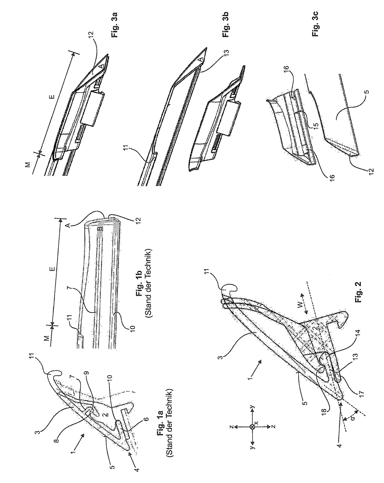
[0030]FIG. 1a shows an edge trim strip 1 with a bridging component 2 mounted on it at the back side, as is known in the prior art. FIG. 1b shows an end section of the edge trim strip 1 in a rear view without the bridging component.

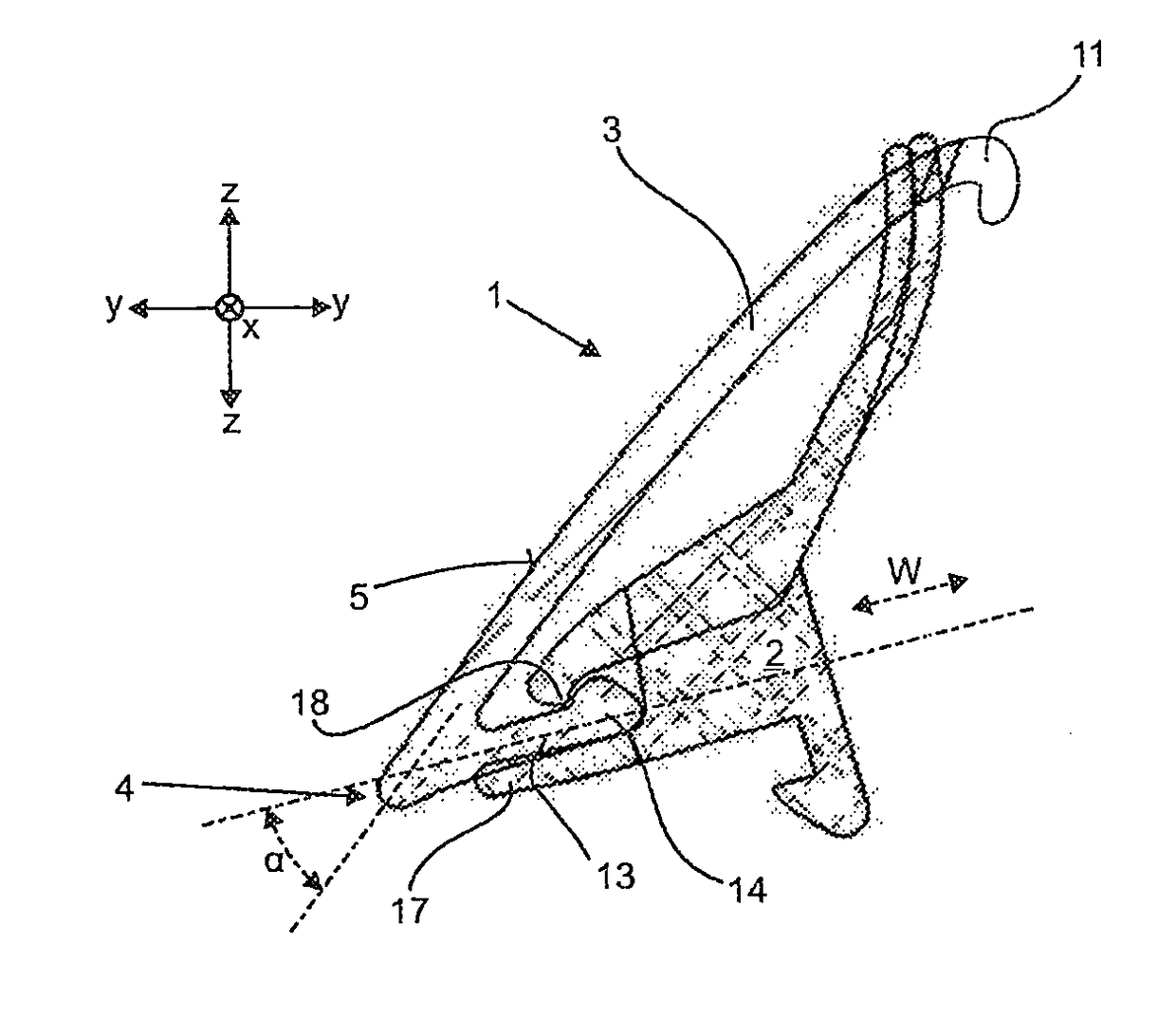
[0031]The edge trim strip 1 has a base leg 3, which forms by its outwardly facing surface when mounted as intended on the motor vehicle an outwardly visible decorative surface 5. The decorative surface is bounded at the bottom side by a lower visible edge 4. Starting from this lower edge, an auxiliary leg 6 extends inwardly.

[0032]The bridging component 2 on the one hand engages by a locking protrusion 8 with the locking lug 9 of a middle web 7 extending inwardly from the back side of the base leg 2 and on the other hand is braced by a bearing 10 against the auxiliary leg 6. Thus, for the interlocking of the bridging component 2 on the edge trim strip 1, the bearing 10 and locking protrusion 8 interact with the auxiliary leg 6 and middle web 7.

[0033]It is e...


PUM


Abstract

In a system made from an edge trim strip and a bridging component for the bridging, especially in optical manner, of a structural transition between the edge trim strip and the bridging component, a simple and secure connection of the edge trim strip and the bridging component should be made possible with the simplest possible fabrication and design of the edge trim strip. The securing of the bridging component to the edge trim strip is accomplished solely by a fastening leg provided on the edge strip and forming an undercut, and the fastening leg is the sole leg of the cross section profile of the edge trim strip serving to secure the bridging component. The bridging component has a locking means in the form of a locking groove, which is able to engage at top and bottom with the fastening leg provided with the undercut in a locking manner.

Description

INTRODUCTION[0001]The invention concerns a bridging component which is designed for bridging, especially in optical manner, of a structural transition from an edge trim strip closing off the window shaft of a vehicle door of an automobile and an adjoining neighbouring part. The invention moreover concerns such an edge trim strip as well as a system made from an edge trim strip and a bridging component.[0002]In automobiles, especially passenger cars, the upper edges of the window shafts into which the window panes descend when they are let down are provided with edge trim strips, which optically close off from the outside the respective window shaft as decorative strips. In this way, the edge trim strips create an optically pleasing termination of the window shaft and distinguish in a not insignificant manner the external appearance of the vehicle thanks to their generally different colour and / or surface configuration from the vehicle body, e.g. as chrome, aluminum or stainless steel...

Claims


Application Information

Patent Timeline
Patent Type & Authority Applications(United States)
IPC IPC(8): B60R13/02
CPCB60R13/02B60R13/06B60J10/70B60J5/0493B60R13/04B60J10/265
Inventor SCHULTE, FRANKIFFLAND, DENNISWINKHAUS, KAISTEIN-HORICH, MARGIT
Owner DURA AUTOMOTIVE HLDG U K LTD
Why Eureka
Try Eureka