
Pivoting mechanism

a technology of rotating mechanism and rotating plate, which is applied in the direction of casings/cabinets/drawers, casings/cabinets/drawers, instruments, etc., can solve problems such as affecting appearance, and achieve the effects of reducing structural interference, increasing freedom, and being convenient to opera

Inactive Publication Date: 2017-05-18
ACER INC
View PDF1 Cites 18 Cited by
  • Summary
  • Abstract
  • Description
  • Claims
  • Application Information

AI Technical Summary

Benefits of technology

The invention provides a pivoting mechanism consisting of a first bracket, second bracket, first crank, and second crank. The second end of the second crank is connected to the first bracket while its opposite end is slidably connected to the second bracket. This results in a nearly-biaxial pivoting mechanism, which allows the two objects to move smoothly with each other and prevents interference between them. This mechanism is connected between the first and second bodies of an electronic device. It allows for smoother pivoting of the bodies and avoids movement paths that could interfere with the pivoting. This improves the operation and appearance of the electronic device.

Problems solved by technology

However, such electronic devices with one single rotary shaft usually have a small unfolded angle.
Even though some may be able to provide a large-angle pivoting function, they may have a noticeable mechanism outside the bodies due to structural interference, which affects the appearance.
Therefore, how to achieve a large-angle pivoting function without sacrificing the appearance (i.e. a hidden mechanism) to improve the convenience of use of the electronic devices is an issue that needs to be addressed.

Method used


Image

  • Pivoting mechanism
  • Pivoting mechanism
  • Pivoting mechanism

Examples


Embodiment Construction

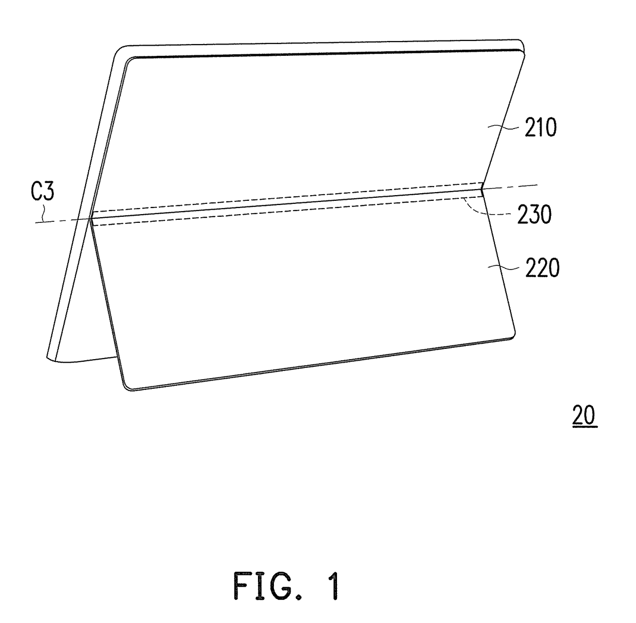
[0017]FIG. 1 is a schematic view showing an electronic device according to an embodiment of the invention. With reference to FIG. 1, an electronic device 200 as shown in the figure is a tablet computer, for example, and includes a first body 210 and a second body 220, wherein the second body 220 may be pivoted or rotated with respect to the first body 210 along an axis C3 through pivoting members (not shown here but will be described in detail later) disposed in a pivoting region 230, and when the first body 210 and the second body 220 are unfolded with respect to each other (a state where the second body 220 and the first body 210 are unfolded to be even after the second body 220 is closed and accommodated, as indicated by the one-way arrow in FIG. 1), a gap between the structures (the first body 210 and the second body 220) is minimized.

[0018]Nevertheless, the invention is not intended to limit the type of the electronic device 200, and a pivoting mechanism of the invention (will ...


PUM


Abstract

A pivoting mechanism, including a first bracket, a second bracket, at least one first crank, and at least one second crank, is provided. The first bracket connecting a first body of an electronic device has a first slot. The second bracket connecting a second body has a second slot. The first crank has a first end slidably and rotatably coupled to the first slot, a second end pivoted to the second bracket, and a first pivoting portion. The second crank has a third end slidably and rotatably coupled to the second slot, a fourth end pivoted to the first bracket, and a second pivoting portion. The first and second pivoting portions are connected to form a rotation center, such that the first and second cranks are rotated about the rotation center and the first and second ends slide in the first and second slots respectively.

Description

CROSS-REFERENCE TO RELATED APPLICATION[0001]This application claims the priority benefit of Taiwan application serial no. 104137828, filed on Nov. 17, 2015. The entirety of the above-mentioned patent application is hereby incorporated by reference herein and made a part of this specification.BACKGROUND OF THE INVENTION[0002]Field of the Invention[0003]The invention relates to a pivoting mechanism.[0004]Description of Related Art[0005]Electronic devices, such as the traditional laptop computers, mobile phones, PDA, digital cameras, and electronic books, that can be folded and unfolded are usually provided with a single rotary shaft between different bodies, such as the main body and the screen, or the body and a support frame. The rotary shaft can be driven to rotate by a force for folding or unfolding the bodies, so as to facilitate use and storage of the electronic devices. However, such electronic devices with one single rotary shaft usually have a small unfolded angle. Even thoug...

Claims


Application Information

Patent Timeline
Patent Type & Authority Applications(United States)
IPC IPC(8): E05D3/18H05K5/02E05D5/06
CPCE05D3/18E05D5/06H04M1/0227E05Y2900/606G06F1/1681H05K5/0226E05D3/186H04M1/022H04M1/0237G06F2200/1633E05Y2999/00
Inventor HONG, SYUAN-HUICHEN, SHUN-BINWU, MING-YEN
Owner ACER INC
Learn More