Luminaire

a technology of a luminaire and a sidewall is applied in the field of luminaires, which can solve the problems of reducing requiring a relatively large thickness, and a relatively high sidewall, so as to reduce the risk of early failure of electronic components and reduce the thickness/height impression

Active Publication Date: 2017-05-18
SIGNIFY HLDG BV
View PDF12 Cites 4 Cited by
  • Summary
  • Abstract
  • Description
  • Claims
  • Application Information

AI Technical Summary

Benefits of technology

[0004]It is an object of the invention to provide a luminaire of the type as described in the opening paragraph in which the abovementioned disadvantage is counteracted. Thereto the luminaire further comprises a first edge of the sidewall bordering the first main face, the sidewall comprises a light emission window which is transmissive for light source light and which has a height H, with H>0 and <W, for example with H in between 0.1*W to 0.8*W, the light exit window is associated with a first light source and the light emission window is associated with a second light source . By these measures the luminaire renders to have a reduced thickness / height impression compared to its actual physical height / thickness. Yet in the inventive luminaire, ample room is available for the accommodation of luminaire components and the risk on early failure of electronic components is reduced because heat generating / dissipating components and heat sensitive (electrical) components can be positioned relatively remote from each other. As the electric components can be arranged inside the housing at ones desire, elongated wiring can be obviated.
[0006]The effect of light being issued from the sidewall is that it masks the actual height of the luminaire as edges of the sidewall are difficult to perceive and / or that it seems that the light exit window of the first main surface is extended with the light emission window of the sidewall. The quality of this effect depends on the balance between the luminous flux from the light exit window of the first main face, the ambient light level and the luminous flux from the light emission window of the sidewall as well as from the distance and size of the light emission window from the light exit window.
[0008]An embodiment of the luminaire of the invention is characterized in that H is in between 0.2*W to 0.4*W. This renders the luminaire to have an even more slim appearance, and yet H is sufficient to mask at least one edge with only limited risk on glare and with H still being relatively small. Thereto the light level at the light emission window preferably is a few times higher than the ambient light level, for example at least 10 times higher. The height H could be constant over the length L of the sidewall or, alternatively, the height H is variable over the length L of the sidewall. In the case of a variable height H, the height could be adapted to the shape of the first main face of the pendant luminaire. For example, in the case of an elongated rectangular first main face, the height H of the light emission window could be decreasing, for example in its length direction, towards the corners of the rectangle, suggesting a tapering construction of the luminaire and hence rendering the luminaire to look more sophisticated.
[0010]The risk on glare should be taken in consideration and being avoided, for example by an appropriate setting of the luminous flux issued via the light emission window or by a directionality below critical angles of 65° between the normal to the light exit window and the (main direction of the) light beam as issued from the light emission window. This can be obtained, for example, by providing the light emission window with a refractive / reflective structure, for example a grating, a Fresnel lens, a meso-optic structure or a micro-lens optic, which at the light emission window redirects the light source light into the desired direction, or alternatively by providing the light source with optics, for example a parabolic reflector / collimator which results in a narrow beam of light source light in the desired direction towards the light emission window. It could be favorable to have low light level light emission from the light emission window at angles larger than 65° to generate a subtle ambient lighting without causing glare. Furthermore, such low brightness emission from the light emission window enables a simple check from relatively large distances from the luminaire on the operation state of the light sources, i.e. if the light sources of the luminaire are switched on / off.
[0011]An embodiment of the luminaire is characterized in that the first light source has main light issue direction towards the light exit window and that the second light source has a main light issue direction towards the light emission window. Easier control of light intensity is than obtained and a larger range of light intensity settings is than enabled. Yet an embodiment of the luminaire is even more preferred which is characterized in that the first and second light source are independently controllable, for example and preferably, in that the first and second light sources have separate electrical connections and / or are mounted on respective, separate PCB's. The level and ratio in luminous flux as issued from the light exit window and light emission window is then even more easily adjustable to the ambient conditions and hence the desired masking effect can even more easily be optimized.
[0015]An embodiment of the luminaire according to the invention is characterized in that the housing comprises acoustic absorptive material. In particular acoustic absorptive luminaires are relatively thick, their thickness being required to obtain sufficiently reduction of undesired noise / sound, and the inventive measures renders these types of luminaires to look thinner and more aesthetically attractive.

Problems solved by technology

It is a known problem with these types of luminaries that a relatively large thickness, i.e. a relatively high sidewall, is required, for example, because of the space required to accommodate luminaire components such as voluminous, acoustic material, light sources, wiring, electronics, heat sinks etc.
However, due to the large width, or height or thickness of the sidewall of these pendant luminaries, the issue arises that people working below these pendant luminaires feel uncomfortable because of the impression of rather heavy and thick luminaires being suspended over their heads.
However, this solution involves the disadvantages of elongated wiring and relatively little room being available for the accommodation of luminaire components with the subsequent risk on early failure of electronic components because heat generating or heat dissipating component, for example heat sinks, and heat sensitive electrical components are positioned relatively close to each other.

Method used


Image

  • Luminaire
  • Luminaire
  • Luminaire

Examples


second embodiment

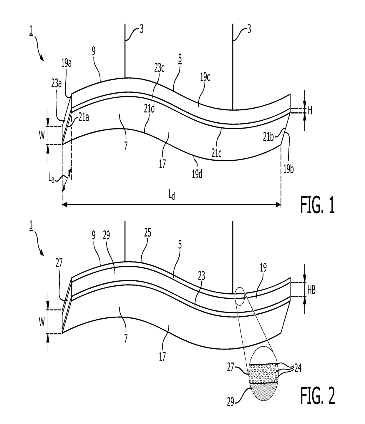
[0029]FIG. 2 shows a perspective view from below of a pendant luminaire 1 according to the invention. The luminaire comprises a housing 5 having a first main face 7 opposite a second main face 9 at a distance W and which housing accommodates a light source (not shown) for generating light source light (not shown). The first main face comprises a light exit window 17 and the second main face 9 comprises a further light exit window 25. The sidewall 19 comprises light emission windows 23 and a further light emission window 27 mutually separated by a light blocking band 29 having a height HB of 0.55*W. The further light emission window is formed by a large number, in this case about 25000, of relatively small light transmissive sub-windows 24 embodied as round dots. From relatively large distances these sub-windows merge into one large light emission window and virtually form one light transmissive area, while when being observed form relatively small distances they render the luminaire...

third embodiment

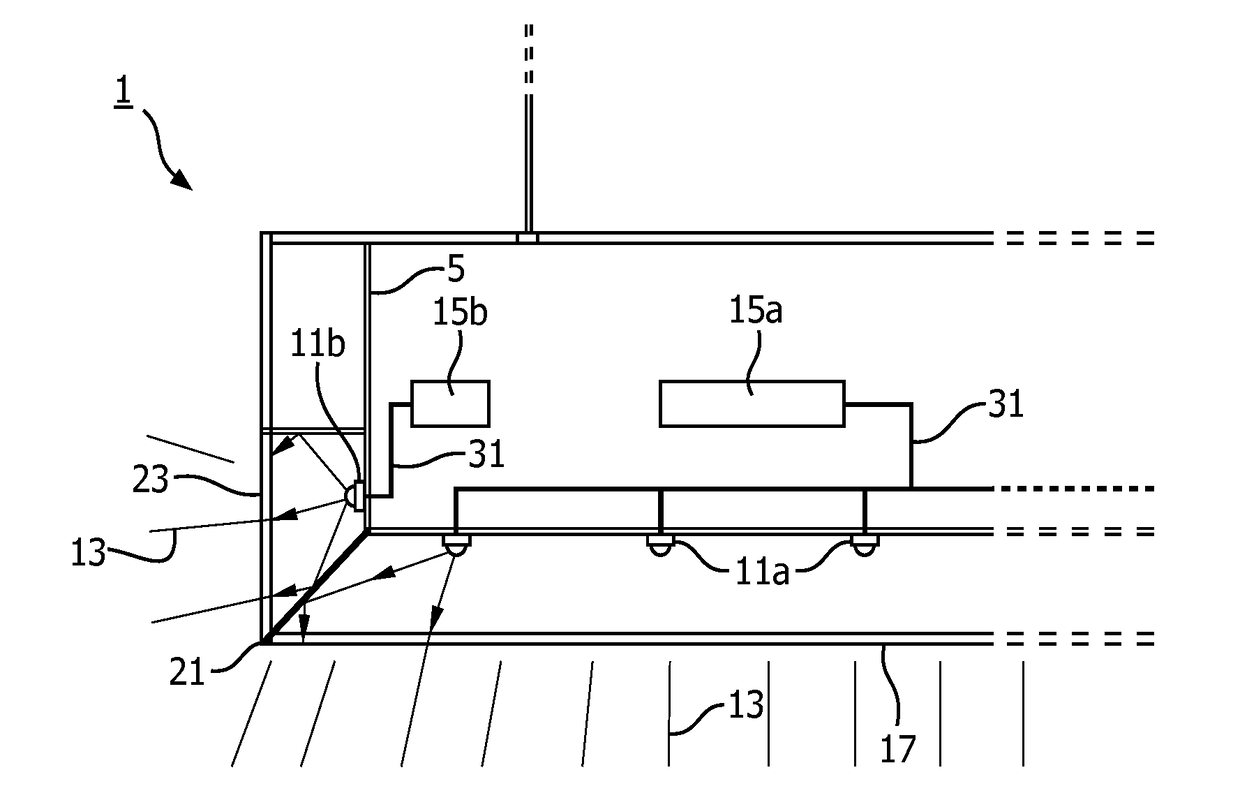
[0030]FIG. 3 shows a partial cross-section in length direction of a luminaire 1 according to the invention. The luminaire has a housing 5 in which a light source 11, i.e. in the figure an array of first Lambertian LED light sources 11a and an array of second Lambertian LED light sources 11b, is accommodated. The luminaire further has a light exit window 17 associated with the array of first light sources and has a light emission window 23 associated with the array of second light sources. The light emission window borders with its first edge 21 the light exit window. Each array of light sources is controlled by a respective controller 15a,b to independently control the intensity / brightness of the associated array of light sources and thus to independently control the luminous flux of light source light 13 to be issued from the light exit window respectively the light emission window. Wiring 31 can be relatively short as the controller can be located close to its associated light sou...

fourth embodiment

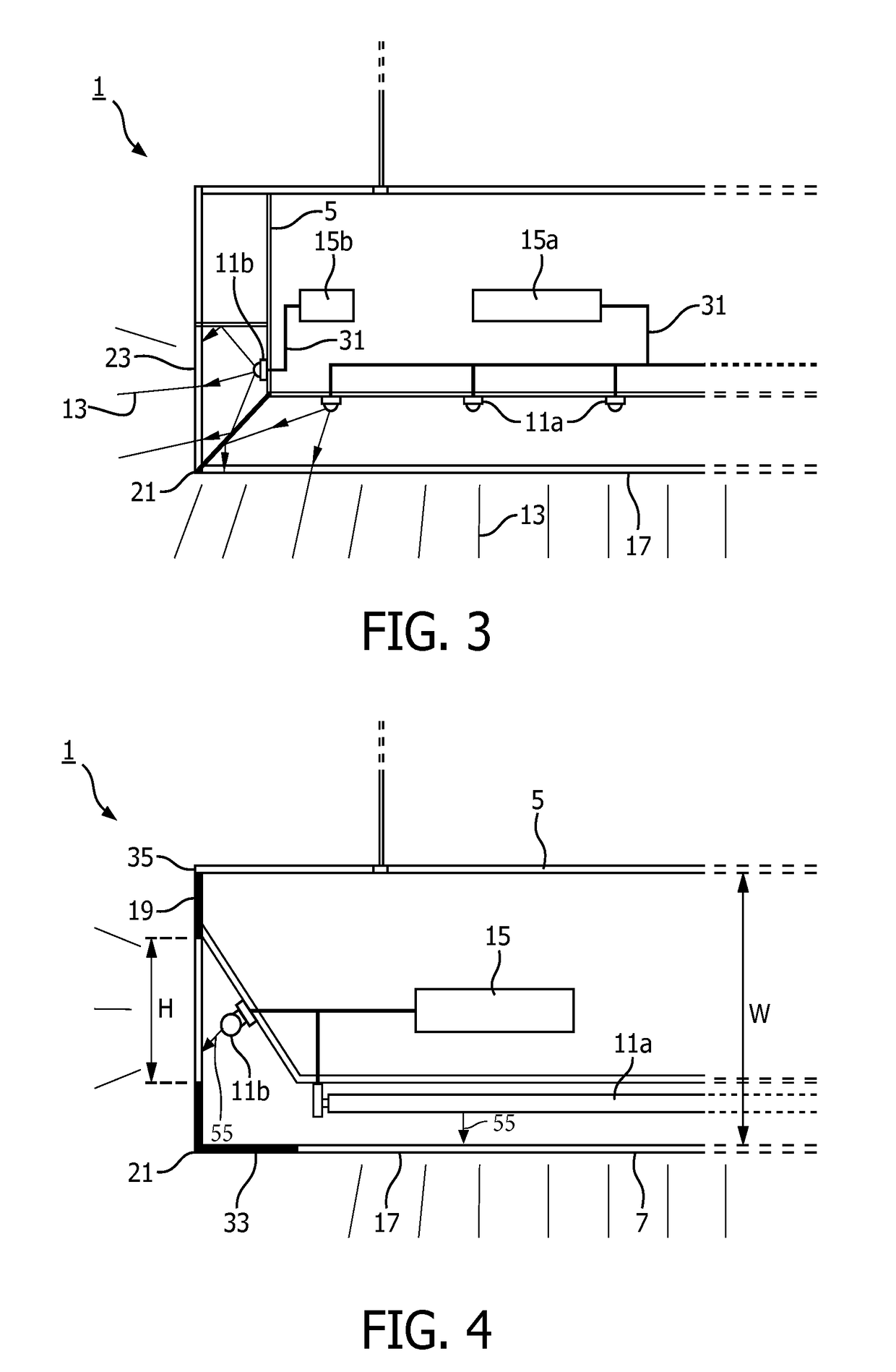
[0031]FIG. 4 shows a partial cross-section of a luminaire 1 according to the invention similar to the cross section of FIG. 3. The light source 11 is accommodated in the housing 5 and in this embodiment comprises a pair of first elongated fluorescent tubes 11a as a first light source and a pair of second elongated fluorescent tubes 11b as a second light source. The fluorescent tubes 11a and 11b each are provided with a respective reflective coating on a respective side facing away from an associated window to render the fluorescent tubes 11a and 11b to have a main light issuing direction 55 towards the associated window. All the light sources are controlled by a single controller 15 and not independently controllable. The first main face 7 has a light exit window 17 which is surrounded by a circumferential non-light emitting region 33. The sidewall 19 has a light emission window 23 which neither borders neither the first edge 21 nor a second edge 35 of the sidewall, and which has a ...


PUM


Abstract

A luminaire comprising a housing having a first main face opposite a second main face at a distance W. The first main face comprises a light exit window transmissive for light source light, is bordered by at least one sidewall connecting the first and second main face, and has a length L. The sidewall comprises essentially over its full length L a light emission window which is transmissive for light source light and which has a height H, with H in between 0.1*W to 0.8*W.

Description

FIELD OF THE INVENTION[0001]The invention relates to a luminaire comprising a housing with a first main face opposite a second main face at a distance W, the housing being configured to accommodate a light source for generating light source light, the first main face comprising a light exit window transmissive for light source light and being bordered by at least one sidewall having a length L and transversely extending from the first main face.BACKGROUND OF THE INVENTION[0002]A luminaire of the type as described in the opening paragraph is known from EP2634474A1. It is a known problem with these types of luminaries that a relatively large thickness, i.e. a relatively high sidewall, is required, for example, because of the space required to accommodate luminaire components such as voluminous, acoustic material, light sources, wiring, electronics, heat sinks etc. Often these luminaires are applied as pendant luminaires and thereto are suspended from the ceiling to give the impression...

Claims


Application Information

Patent Timeline
Patent Type & Authority Applications(United States)
IPC IPC(8): F21S8/06F21V3/00F21V5/00F21V7/00F21V15/01
CPCF21S8/061F21V7/0016F21V15/01F21V5/002G10K11/162F21Y2103/00F21Y2105/10F21Y2113/20F21Y2115/10F21V3/00F21S8/06F21Y2113/00
Inventor FERRARI, ELENA TIZIANADE GIER, RONALD CORNELISBOOIJ, SILVIA MARIA
Owner SIGNIFY HLDG BV
Why Eureka
Try Eureka