Powder container, image forming apparatus, and nozzle receiver

Active Publication Date: 2017-05-18
RICOH KK
View PDF0 Cites 4 Cited by
  • Summary
  • Abstract
  • Description
  • Claims
  • Application Information

AI Technical Summary

Benefits of technology

[0005]According to an embodiment, when a nozzle insertion member is detached from a powder container, an engaging portion and an engaged portion are disengaged from each other by resiliently displacing the engaging portion in a direction in which the engaging portion is disengaged from the engage

Problems solved by technology

However, at the time of detachment, the nozzle insertion member and the powder storage are stress

Method used


Image

  • Powder container, image forming apparatus, and nozzle receiver
  • Powder container, image forming apparatus, and nozzle receiver
  • Powder container, image forming apparatus, and nozzle receiver

Examples


Example

[0027]Embodiments of the present'invention will be described below with reference to the accompanying drawings. In the drawings, Y, M, C, and K are symbols appended to components corresponding to yellow, magenta, cyan, and black, respectively, and will be omitted appropriately.

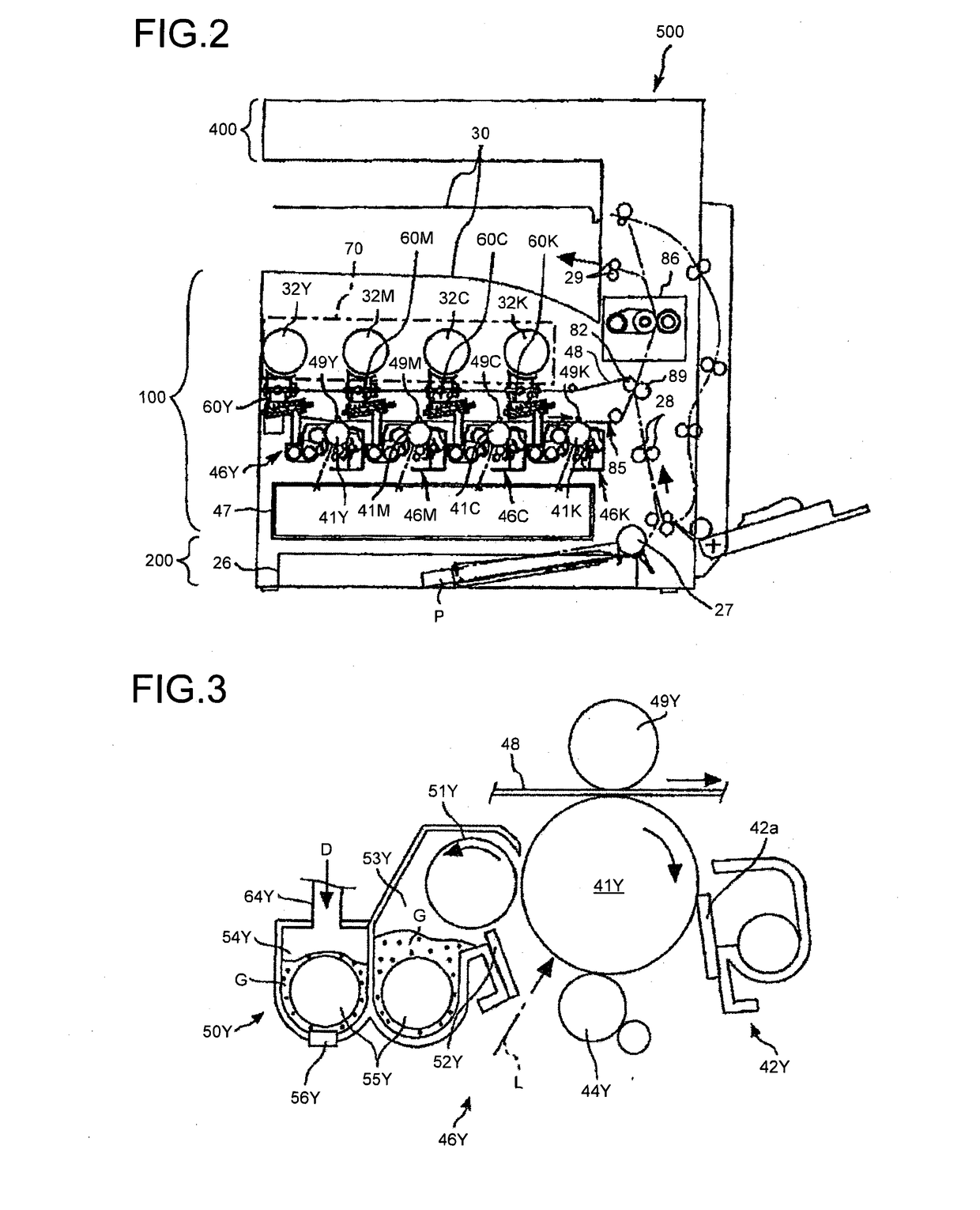
[0028]FIG. 2 is an overall configuration diagram of an electrophotography tandem-type color copier (hereinafter, referred to as “a copier 500”) serving as an image forming apparatus according to an embodiment. The image forming apparatus may be a monochrome copier; The image forming apparatus may be a printer, a facsimile machine, or a multifunction peripheral with multiple functions of a copier, a printer, and a facsimile machine, instead of the copier.

[0029]The copier 500 mainly includes a copier main-body (hereinafter, referred to as “a printer 100”), a sheet feed table (hereinafter, referred to as “a sheet feeder 200”), and a scanner section (hereinafter, referred to as “a scanner 400”) mounted on the prin...


PUM


Abstract

According to an embodiment, when a nozzle insertion member is detached from a powder container, an engaging portion and an engaged portion are disengaged from each other by resiliently displacing the engaging portion in a direction in which the engaging portion is disengaged from the engaged portion. Therefore, it is possible to reduce a stress applied to the powder container and the nozzle insertion member at the time of attachment and detachment of the nozzle insertion member. Consequently, it becomes possible to easily detach the nozzle insertion member from the powder container.

Description

TECHNICAL FIELD[0001]The present invention relates to a powder container for storing developer that is powder used in an image forming apparatus, such as a printer, a facsimile machine, a copier, or a multifunction peripheral with multiple functions of the printer, the facsimile machine, and the copier, and an image forming apparatus including the powder container.BACKGROUND ART[0002]In an electrophotography image forming apparatus, a powder conveying device (toner replenishing device) supplies (replenishes) toner that is developer from a toner container serving as a powder container containing the developer that is powder to a developing device. The toner container includes a rotatable cylindrical powder storage, a nozzle insertion member attached to the powder storage, an opening provided on the nozzle insertion member, and an opening / closing member that moves to a closing position at which the opening is closed and to an opening position at which the opening is opened along with ...

Claims


Application Information

Patent Timeline
IPC IPC(8): G03G15/08
CPCG03G15/0877G03G15/0872G03G15/0879
Inventor YANO, KEIICHIYAMABE, JUNJITERANISHI, RYOICHITANAKA, YUUTATERAZAWA, SEIJI
Owner RICOH KK
Why Eureka
Try Eureka