Piezoelectric actuator, stacked actuator, piezoelectric motor, robot, hand, and liquid transport pump
a piezoelectric actuator and actuator technology, applied in the direction of positive displacement liquid engines, manufacturing tools, generators/motors, etc., can solve the problems of external damage, affecting the function of piezoelectric bodies, and affecting the piezoelectric actuator
- Summary
- Abstract
- Description
- Claims
- Application Information
AI Technical Summary
Benefits of technology
Problems solved by technology
Method used
Image

Examples
first embodiment
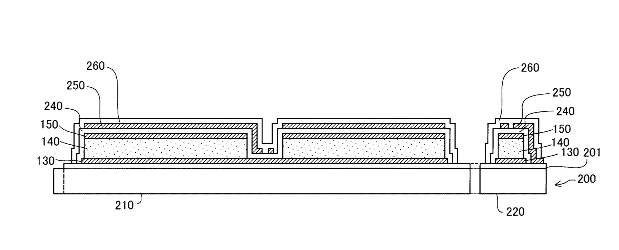
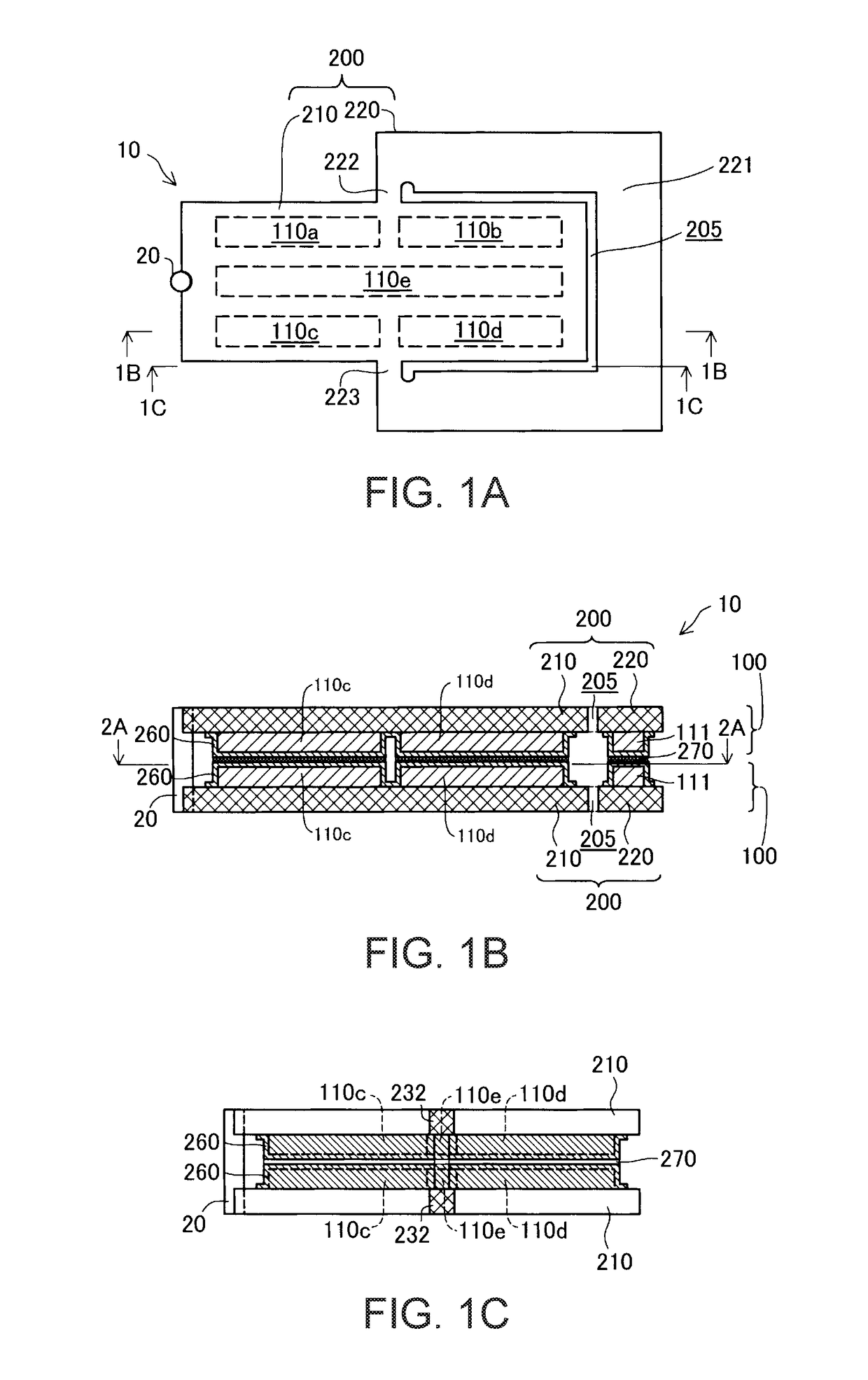
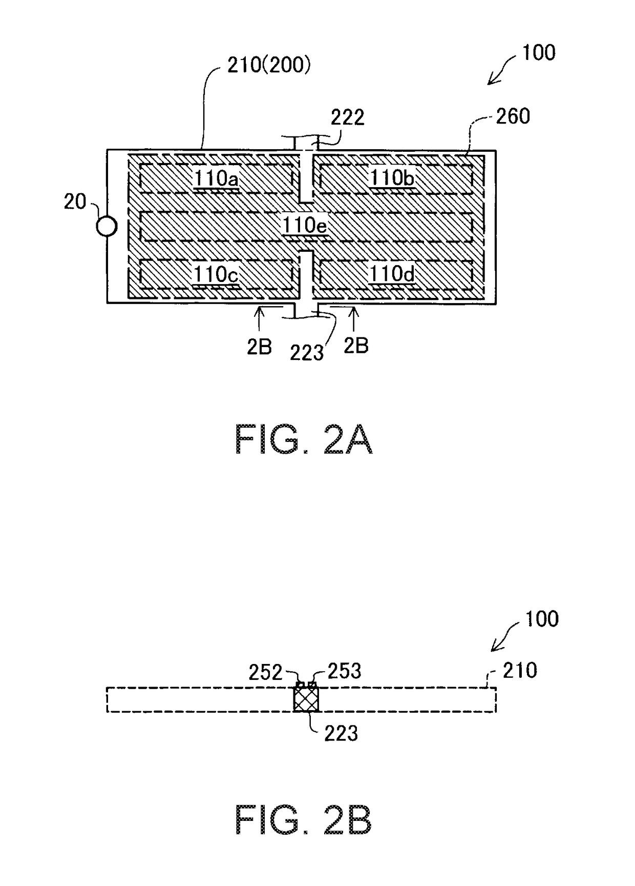
[0038]FIG. 1A is a plan view illustrating a schematic configuration of a piezoelectric actuator 10. The piezoelectric actuator 10 includes piezoelectric elements 110a, 110b, 110c, 110d, and 110e, a substrate 200, and a projection member 20. The substrate 200 includes a vibrating portion 210 and a support portion 220 that supports the vibrating portion 210. The vibrating portion 210 has an approximately rectangular shape in which the piezoelectric elements 110a, 110b, 110c, 110d, and 110e are arranged. The piezoelectric element 110e is configured to have an approximately rectangular shape and is configured to extend in the longitudinal direction of the vibrating portion 210 at the widthwise center of the vibrating portion 210. The piezoelectric elements 110a, 110b, 110c, and 110d are configured to be positioned at four corners of the vibrating portion 210. The support portion 220 is configured to surround approximately half of the vibrating portion 210, and end portions of the suppor...
second embodiment
[0070]FIG. 12 is a descriptive diagram illustrating a piezoelectric actuator 11 of a second embodiment. While the piezoelectric actuator10 of the first embodiment includes two piezoelectric actuator units 100, the piezoelectric actuator 11 of the second embodiment includes only one piezoelectric actuator unit 100 and, instead of the second piezoelectric actuator unit 100 of the first embodiment, includes the substrate 200 on which piezoelectric elements are not arranged. That is, the piezoelectric elements 110a to 110e of the first piezoelectric actuator unit 100 are sandwiched between the substrate 200 of the first piezoelectric actuator unit 100 and the substrate 200 on which piezoelectric elements are not arranged.
[0071]The piezoelectric actuator 11 of the second embodiment includes two substrates 200, the piezoelectric elements 110a to 110e that are arranged between the two substrates 200, and the cladding portion 260 that covers at least a part of the surrounding area of the pi...
third embodiment
[0072]FIG. 13 is a descriptive diagram illustrating a stacked actuator 12 of a third embodiment. The piezoelectric actuator 10 is described in the first embodiment. The piezoelectric actuator 10 may be used in multiple quantities and be stacked in the direction normal to the surface of the substrate 200 to configure the stacked actuator 12. The piezoelectric actuator 11 of the second embodiment as well may be used in multiple quantities and be stacked in the direction normal to the surface of the substrate 200.
Other Embodiments
[0073]The piezoelectric actuator 10 described above can exert large force on the driven member using resonance and is applicable to various apparatuses. The piezoelectric actuator 10 can be used as a drive device in various apparatuses such as a robot (includes an electronic component transport apparatus (IC handler) as well), a pump for medication administration, a calendar advancing apparatus for a timepiece, and a printing apparatus (for example, a paper fe...
PUM
 Abstract
Description
Claims
Application Information
 - Generate Ideas
- Intellectual Property
- Life Sciences
- Materials
- Tech Scout
- Unparalleled Data Quality
- Higher Quality Content
- 60% Fewer Hallucinations
Browse by: Latest US Patents, China's latest patents, Technical Efficacy Thesaurus, Application Domain, Technology Topic, Popular Technical Reports.
© 2025 PatSnap. All rights reserved.Legal|Privacy policy|Modern Slavery Act Transparency Statement|Sitemap|About US| Contact US: help@patsnap.com