
Implant Surfaces

a technology of implants and surfaces, applied in the field of bone replacement implants, can solve the problems of difficult osseointegration, inability of surgeons to effectively place, secure and pack bone grafts behind implants,

Active Publication Date: 2017-05-25
OSSIS CORP
View PDF11 Cites 7 Cited by
  • Summary
  • Abstract
  • Description
  • Claims
  • Application Information

AI Technical Summary

Benefits of technology

The invention is an orthopaedic implant with a surface that includes an area of integrally formed three-dimensional scaffold. The scaffold can be located on every bone apposition surface within the implant and can be designed based on patient-specific information. The scaffold can be formed using additive manufacturing techniques and can be antibacterial. The implant can also include flanges and suture holes. The technical effects of the invention include improved bone growth and reduced bone resorption, as well as improved soft and hard tissue ingrowth.

Problems solved by technology

Some of the disadvantages and problems with current techniques are discussed below with reference to the acetabular region, however such issues are common across all regions where bone replacements are conducted, including the knee, elbow, shoulder to name a few.
Such features include the polished surfaces present in common bone implants that make osseointegration difficult, sub-optimal levels of surface scaffolding associated with the implant, difficulty in positioning and alignment of the implant, or structural disadvantages that result in the inability of the surgeon to effectively place, secure and pack bone graft behind the implant.

Method used


Image

  • Implant Surfaces
  • Implant Surfaces
  • Implant Surfaces

Examples


Embodiment Construction

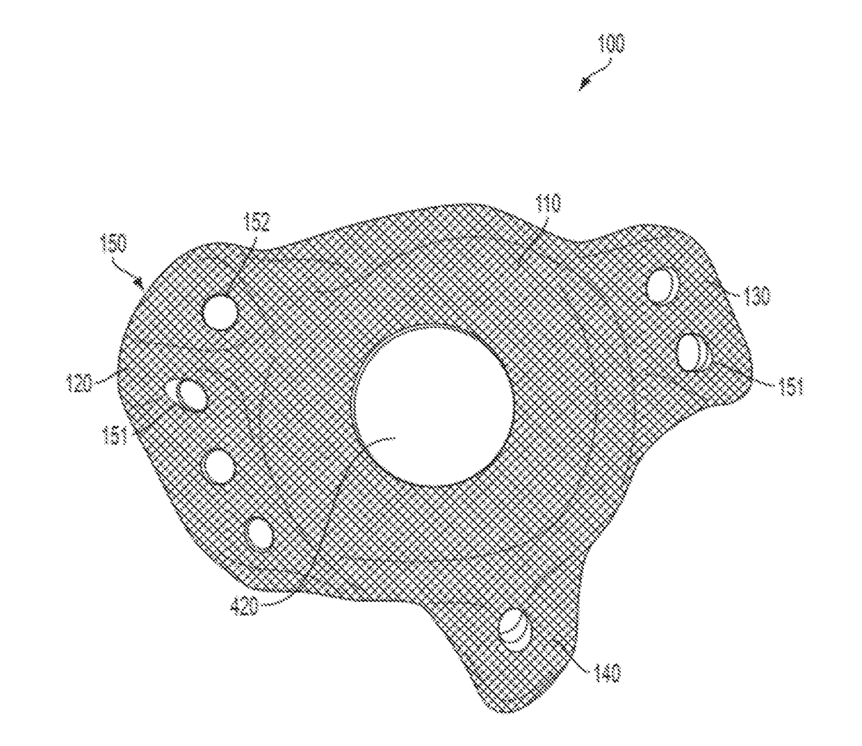
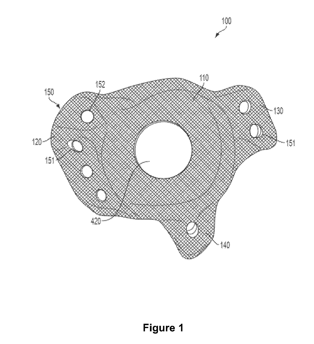
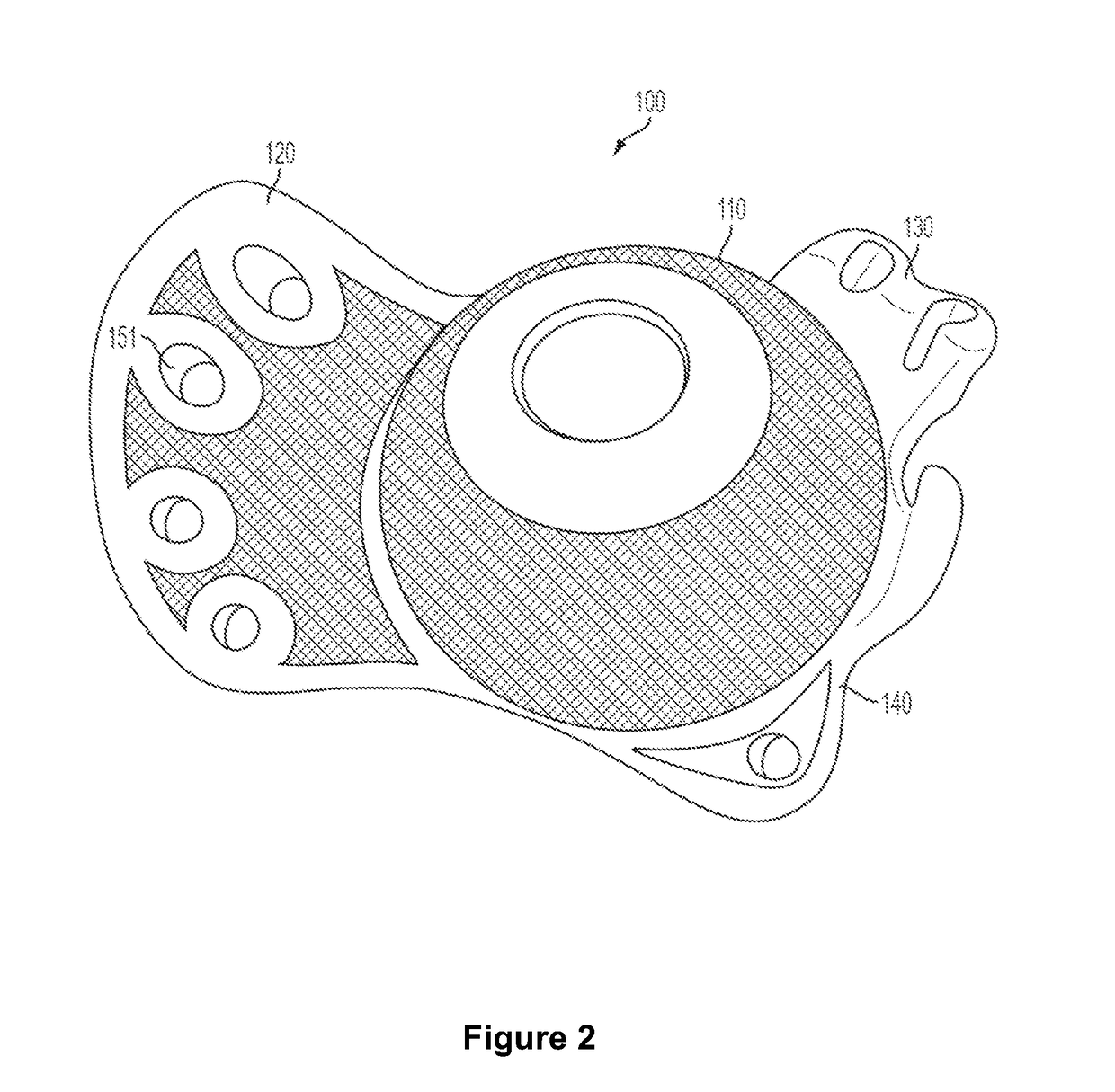
[0182]The implant, systems and methods of the present invention are described in further detail below and with reference to FIGS. 1-8.

[0183]The orthopaedic implants described in the current invention may be applied to a range of bone implants and implants, designed for use in any number of regions in the body and may also be applied to implants of varying shapes and sizes.

[0184]In a preferred aspect of the invention the implants and methods of the present invention are for use in acetabulum implants. However, this use is not intended to be limiting and as would be understood by a person skilled in the art, the methods, implant and systems described herein may include a range of implant designs and locations as necessary. The following description will for exemplary purposes be described in relation to an acetabular implant and associated methods.

[0185]The figures include acetabular implants designed for both left and right hip replacements and therefore some figures will differ in o...


PUM


Abstract

The implants of the invention relate to improved implants formed using additive manufacturing techniques, the implants including a hemispherical cup portion, and an ischium flange, a pubic ramus flange and an ilium flange, each flange extending outwardly from the perimeter of the hemispherical cup portion, wherein the implant surface includes an area of integrally formed three dimensional scaffold on the bone apposition surfaces of the cup portion and on a bone apposition surface of at least one of the flanges of the implant. The invention also relates to implants with different surface texture and alignment features, together with methods for the manufacture of patient-specific implants of the invention.

Description

CROSS-REFERENCE TO RELATED APPLICATIONS[0001]This application is a U.S. National Stage Entry of PCT / NZ2015 / 050057 filed May 14, 2015, which claims the benefit of priority to New Zealand Patent Application No. 625956 filed Jun. 5, 2014, both of which are incorporated in their entireties by reference.TECHNICAL FIELD[0002]This invention relates to improved bone replacement implants, methods for their use and the manufacture thereof.BACKGROUND ART[0003]Successful placement and attachment of an orthopaedic implant to patient bone is essential in securing successful patient outcomes for people undergoing bone replacement surgery.[0004]Some of the disadvantages and problems with current techniques are discussed below with reference to the acetabular region, however such issues are common across all regions where bone replacements are conducted, including the knee, elbow, shoulder to name a few.[0005]Typical acetabular augmentation occurs during the process of total hip replacement. During ...

Claims


Application Information

Patent Timeline
IPC IPC(8): A61F2/34A61F2/30
CPCA61F2/34A61F2002/30774A61F2/30907A61F2/30771A61F2002/3429A61F2002/3404A61F2002/30914A61F2002/3483A61F2/30744A61F2002/3401A61F2002/30617A61F2002/30688A61F2002/30838A61F2002/30962A61F2002/30787A61F2/30942A61F2002/30578A61F2002/3403A61F2/30767A61F2002/3093A61F2002/3432A61F2240/002
Inventor DUNN, TIMOTHY JOHNBURN, PETER JAMESSMYTH, NICHOLAS MCKENZIE
Owner OSSIS CORP
Learn More