
Components for threading of bone

a bone forming tool and bone technology, applied in dental surgery, ultrasonic/sonic/infrasonic diagnostics, applications, etc., can solve problems such as jamming in the guide sleeve and non-optimal position, and achieve the effect of improving the accuracy of the position of the implant in the bone and uniform load distribution

Active Publication Date: 2016-02-16
NOBEL BIOCARE SERVICES AG
View PDF54 Cites 0 Cited by
  • Summary
  • Abstract
  • Description
  • Claims
  • Application Information

AI Technical Summary

Benefits of technology

The patent describes a way to improve the accuracy of placing an implant in bone and to ensure that it is positioned correctly. This helps to reduce the likelihood of the implant causing complications or requiring revision surgery. The method involves using special implants that can be designed to improve bone growth around the implant, while also minimizing any damage to the bone during the placement procedure. This technique can be particularly useful in cases where the implant needs to be securely positioned in a hard bone.

Problems solved by technology

If, for example, the bone is denser one side of the central longitudinal axis of the implant, it will often deviate towards the softer bone, and end up in a non-optimal position, which is different from a planned position.
If this happens during guided surgery, the implant mount, which is guided by a guide sleeve of the surgical template, may jam in the guide sleeve.

Method used


Image

  • Components for threading of bone
  • Components for threading of bone
  • Components for threading of bone

Examples


Embodiment Construction

[0034]Specific embodiments will now be described with reference to the accompanying drawings. This disclosure may, however, be embodied in many different forms and should not be construed as limited to the embodiments set forth herein; rather, these embodiments are provided so that this disclosure will be thorough and complete, and will fully convey the scope of the invention to those skilled in the art. The terminology used in the detailed description of the embodiments illustrated in the accompanying drawings is not intended to be limiting of the invention. In the drawings, like numbers refer to like elements.

[0035]The following description focuses on certain embodiments of the present disclosure applicable to installing a dental implant in the jawbone. However, it will be appreciated that the invention is not limited to this application but may be applied to many other procedures, such as oral and cranio-maxillofacial implant placement in anywhere in bone in the cranium etc. Cert...


PUM


Abstract

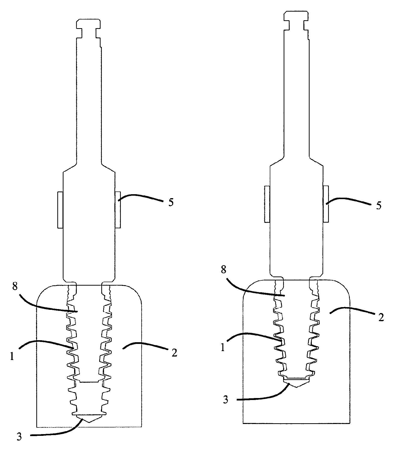
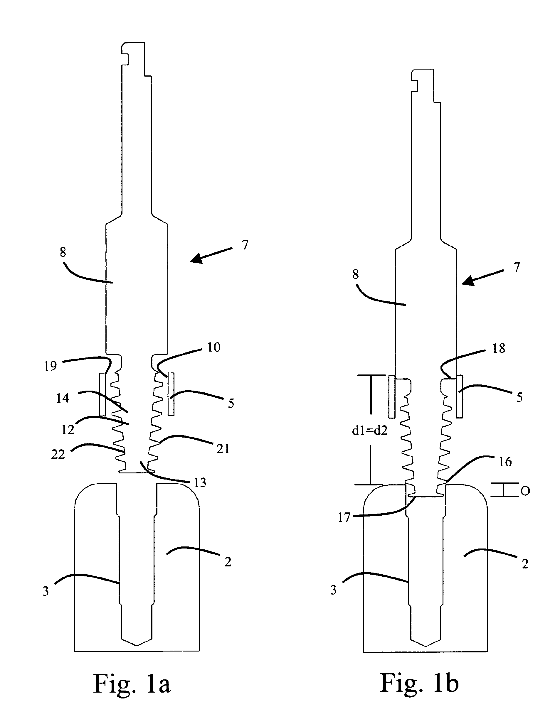
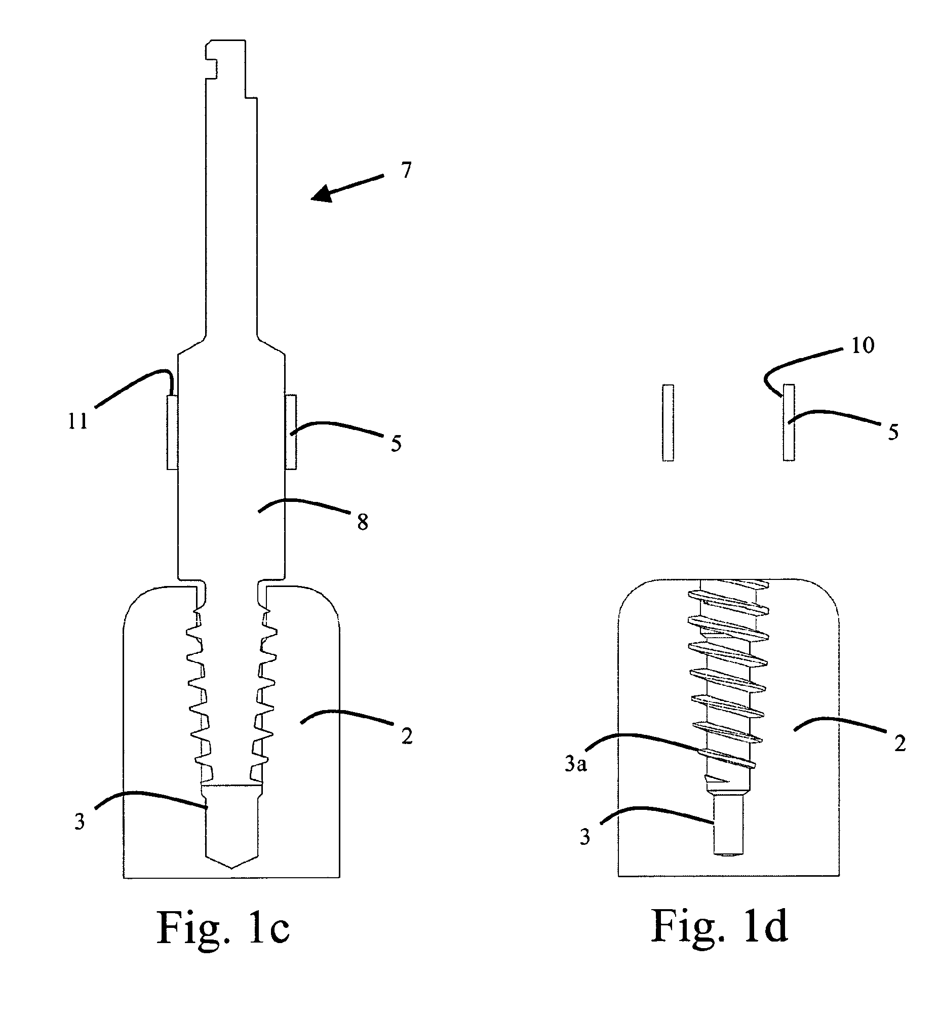
In certain embodiments, a combination of a thread forming tool and an implant is disclosed. The thread forming tool can have a thread forming section with a helical thread having at least one cutting surface for cutting a thread in bone. The implant can include a bone apposition surface having at least one helical thread for position at least partially in the thread of the bone. A longitudinal cross-sectional shape of at least a portion of the helical thread of the thread forming section in certain embodiments, substantially corresponds to a longitudinal cross-sectional shape of at least a portion of the helical thread of the implant.

Description

CROSS-REFERENCE TO RELATED APPLICATIONS[0001]This application is a national stage application under 35 U.S.C. §371 of PCT Application No. PCT / EP2010 / 005449, filed on Sep. 6, 2010, which published in English as WO 2011 / 026644 A1 on Mar. 10, 2011 and which claims priority benefit of European Patent Application No. 09011435.6, filed on Sep. 7, 2009, the entire contents of which applications and publication are herein incorporated by reference in their entirety.BACKGROUND[0002]1. Field of the Invention[0003]This invention pertains in general to the field of implant surgery. More particularly, the invention relates to a combination of a thread forming tool and an implant. The components may be used separately or in a system for drill and implant guided surgery.[0004]2. Description of the Related Art[0005]In certain clinical applications when the implant is placed, such as placement in a jawbone, the implant has a tendency to deviate from its anticipated trajectory, for example due to var...

Claims


Application Information

Patent Timeline
Patent Type & Authority Patents(United States)
IPC IPC(8): A61B8/00A61B17/16A61C8/00A61C1/08
CPCA61C8/0089A61B17/1655A61C1/084A61B17/16A61C1/08A61C3/00A61C3/02A61C8/00A61C8/0018A61C8/0022
Inventor JORNEUS, LARSPETERSSON, HENRIK
Owner NOBEL BIOCARE SERVICES AG
Learn More