
Lighting device

a technology of light emitting device and light emitting profile, which is applied in the direction of electric lighting, fixed installation, lighting and heating apparatus, etc. it can solve the problems of poor life and application of existing headlights, large differences in arrangement positions, and poor efficiency of tungsten filament bulb lamps, so as to reduce the occurrence of scattered light, the effect of preferable light-emitting profile and preferable light-emitting profil

Inactive Publication Date: 2017-05-25
WU CHIA HSIANG
View PDF5 Cites 14 Cited by
  • Summary
  • Abstract
  • Description
  • Claims
  • Application Information

AI Technical Summary

Benefits of technology

The present invention provides a lighting device with two light-emitting components that are positioned on the sidewalls of a substrate, which results in close proximity between the two light-emitting units. This reduces scattered light and generates a more desirable light-emitting profile when the lighting components are positioned on a heat-conducting column. Additionally, the two light-emitting units are commonly placed within the lampshade standard, resulting in a more ideal illumination pattern and simultaneous reduction of scattered light.

Problems solved by technology

However, such tungsten filament bulb lamps have poor efficiency and are prone to damage caused by burn-out of the tungsten filament or breaking of the glass cover.
Thus, lifetime and application of existing headlights are poor.
However, structural limitations of conventional light-emitting diode would result in considerable differences in arrangement position of LED as compared to that of tungsten filament bulb.
Meanwhile, the structure of conventional light-emitting diode would also limit its possible arrangement positions, instead of arranging at any desired position or the original arrangement position of the tungsten filament bulb.
Thus, although the existing vehicle headlights have overcome the problems with tungsten filament bulb, such as short lifetime and breaking of glass cover due to burn-out prone filaments, the light-emitting components would departure from correct illumination position of the lighting device, resulting in occurrence of scattered light not conforming to the desired light profile during light-emission.

Method used


Image

  • Lighting device
  • Lighting device
  • Lighting device

Examples


Embodiment Construction

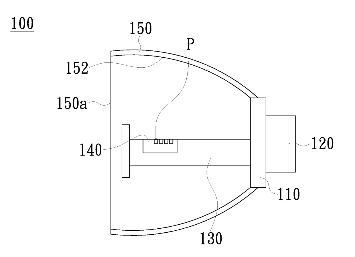
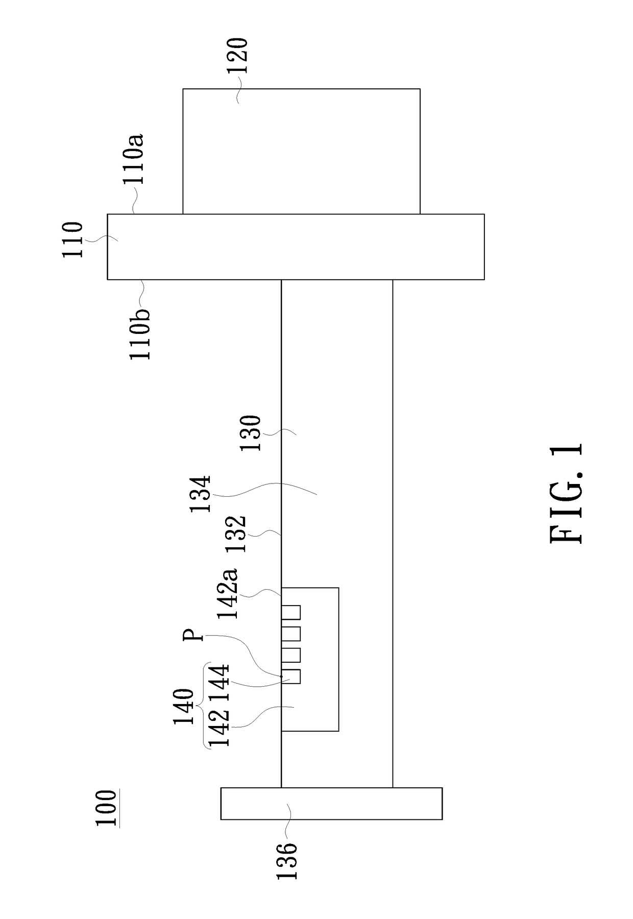
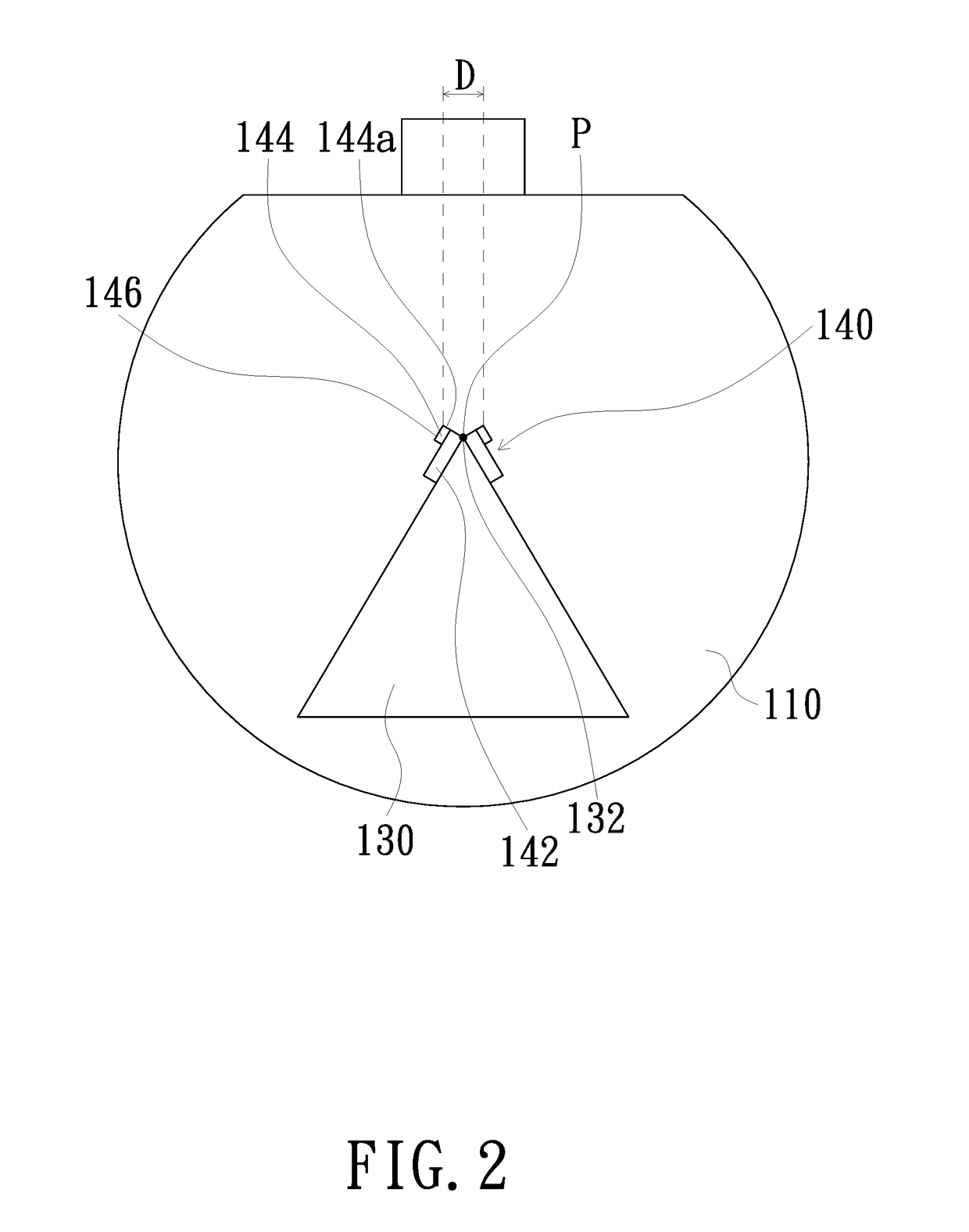
[0030]Referring to FIGS. 1 and 2. FIG. 1 depicts a side view of a lighting device according to an embodiment of the invention, and FIG. 2 depicts a front view of a lighting device of FIG. 1 without a shield. As shown in FIGS. 1 and 2, the present embodiment discloses a lighting device 100, including a base 110, a heat-conducting element 120, a heat-conducting column 130 and two light-emitting components 140. The lighting device 100 as disclosed in the present embodiment is applicable to a vehicle lamp. More particularly, the lighting device 100 as disclosed in the present embodiment is applicable to a vehicle headlamp.

[0031]The base 110 includes a first surface 110a and a second surface 110b opposite to each other. The heat-conducting element 120 is disposed on the first surface 110a of the base 110. For example, the first surface 110a of the base 110 is the surface away from the light-emitting components 140. The heat-conducting element 120 can be externally connected to a starting...


PUM


Abstract

A lighting device includes a base, a heat-conducting element, a heat-conducting column and two light-emitting components. The base includes a first surface and a second surface opposite to each other. The heat-conducting element is disposed on the first surface of the base. One end of the heat-conducting column is disposed on the second surface of the base and connected to heat-conducting element, and the heat-conducting column includes a first edge. The light-emitting components are disposed on two adjacent surfaces of said heat-conducting column separated by said first edge. The light-emitting components include two substrates and two light-emitting units. The substrates are disposed on two opposite sides of said first edge of said heat-conducting column, and each of the substrates includes a sidewall adjacent to the first edge. The light-emitting units are disposed on the substrates, and an outer edge of the light-emitting unit is adjacent to the corresponding sidewall.

Description

FIELD OF THE INVENTION[0001]The invention relates to a lighting device, and more particularly to a lighting device for vehicles.BACKGROUND OF THE INVENTION[0002]In the design of headlights for vehicles, firstly, it should be considered that the front road must be lightened for the driver to distinguish road conditions clearly. Further, illumination safety still should be considered; that is to say, when a car approaches from the front, it will be necessary to prevent vehicle's high-beam light from dazzling the other party's driver, so that the danger caused by the driver overlooking the front road conditions can be avoided. Therefore, there are regulations for vehicle headlights illumination in all countries and regions, i.e. when no car approaches from the front, it is allowed to use a high-beam headlight with a broader illumination area. On the other hand, when a car approaches from the front, it is necessary to switch the headlight into a low-beam light.[0003]Tungsten filament bu...

Claims


Application Information

Patent Timeline
Patent Type & Authority Applications(United States)
IPC IPC(8): F21S8/10
CPCF21S48/1341F21S48/328F21S48/1705F21S48/1388F21S48/115F21S41/148F21S41/151F21S41/192F21S41/321F21S41/36F21S41/365F21S41/435F21S41/60F21S45/48F21S41/331
Inventor WU, CHIA-HSIANG
Owner WU CHIA HSIANG
Learn More