Illuminated Sight System

a technology of illumination and sighting system, which is applied in the field of illumination sighting system for weapons, can solve the problems of tritium coatings that require charging and feature effectiveness in low light situations

Active Publication Date: 2017-05-25
BRIGHTSIGHT LLC
View PDF0 Cites 10 Cited by
  • Summary
  • Abstract
  • Description
  • Claims
  • Application Information

AI Technical Summary

Problems solved by technology

Unfortunately however, these features are not very effective in low light situations.
And although flashlights or lasers mounted to the weapon may help an operator to aim in low light, they ...

Method used


Image

  • Illuminated Sight System
  • Illuminated Sight System
  • Illuminated Sight System

Examples


Embodiment Construction

[0028]In accordance with the present invention, a novel sighting system that is illuminated and configurable for use with weapons and other articles (such as laser targeting systems) is provided and disclose herein. It should be appreciated that the present invention can be configured to operate with unfolding sighting systems currently installed on modern military styled and popular hunting and target rifles. Additionally, if there is sufficient ambient light, the present invention is operable even if the illumination fails to operate

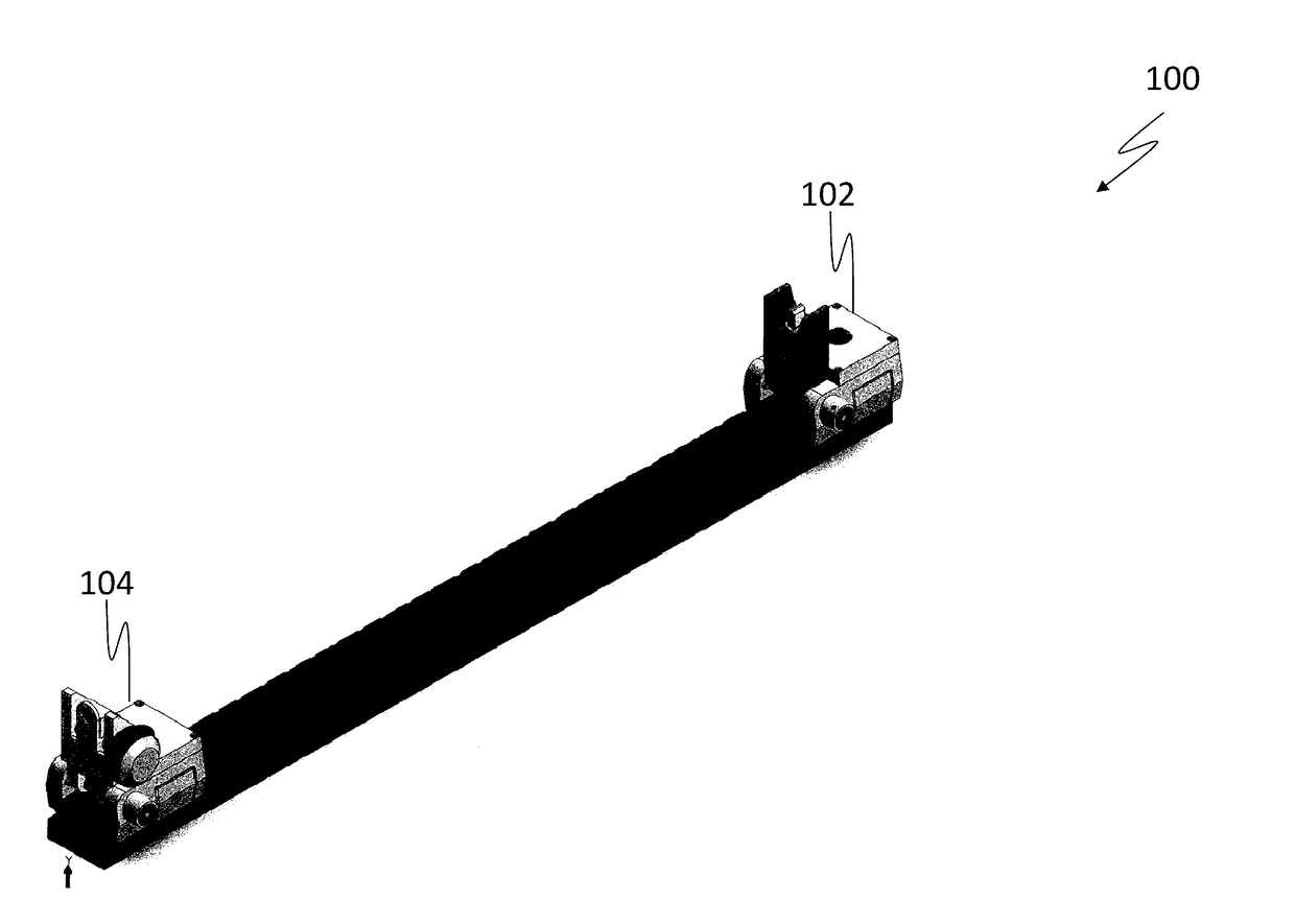
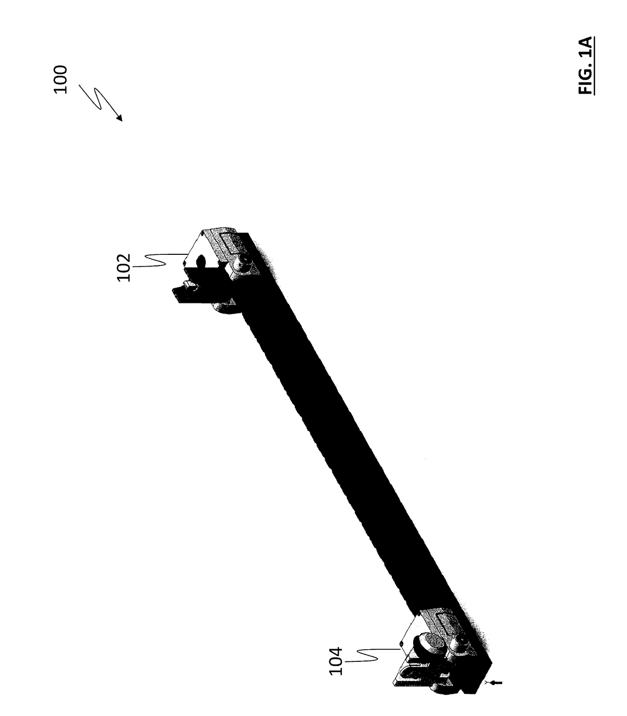
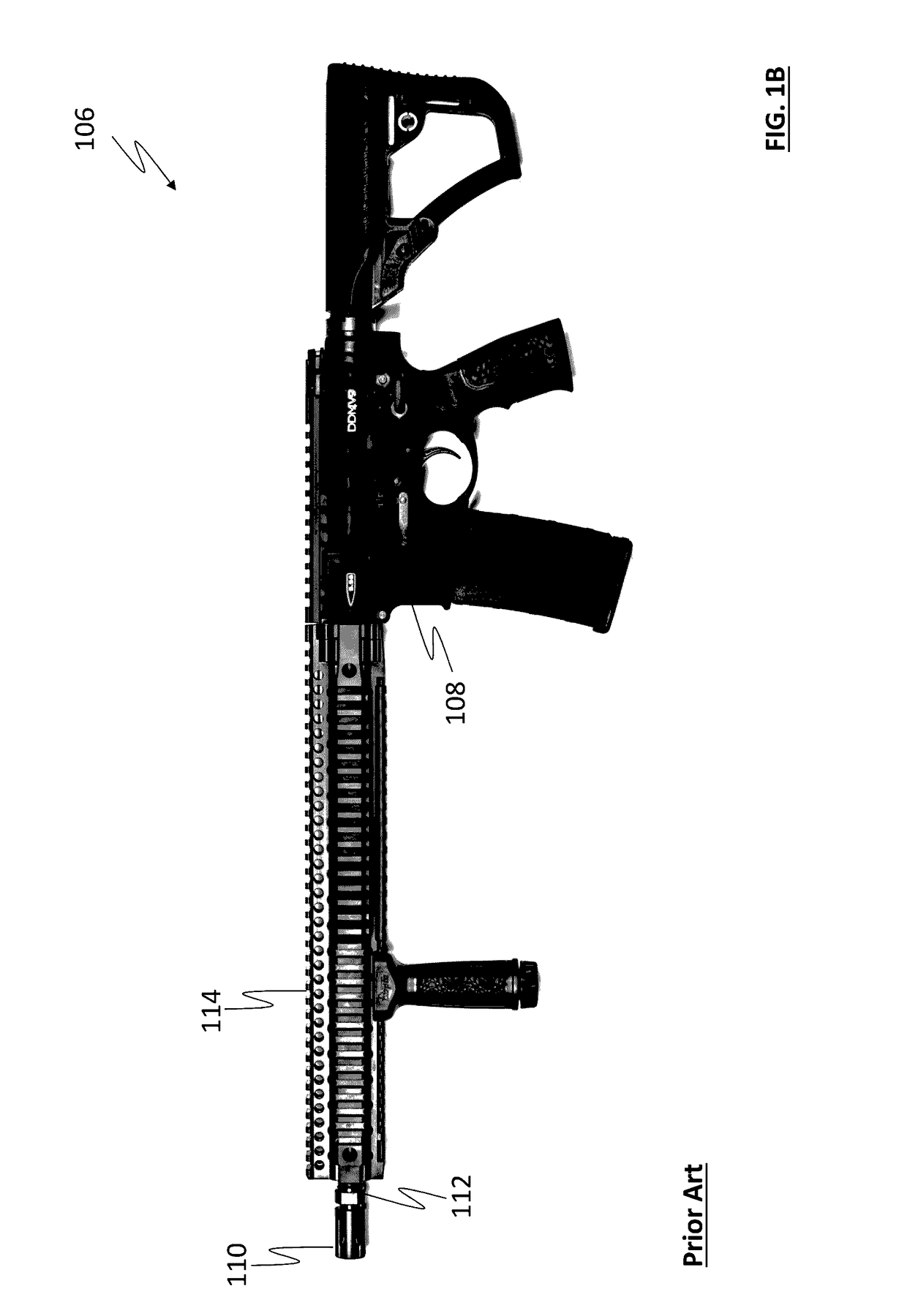
[0029]Referring to FIG. 1A, FIG. 1B and FIG. 1C, an illuminated sighting system 100 is provided and includes a front sight 102 and a rear sight 104, wherein the front sight 102 and rear sight 104 are configured to securely and removably attach to a weapon 106 having a receiver 108, a barrel 110, a barrel muzzle 112 and a mounting rail 114 (such as a picatinny rail or a weaver rail). The mounting rail 114 is typically associated with the weapon 106 such...


PUM


Abstract

An illuminated sighting system is provided and includes a front sight and a rear sight, wherein the front sight includes a front aperture and a front base, wherein, the front aperture further includes a front LED and a front sight post wherein the front sight post is adjustable in height and is optically communicated with the front LED such that when the front LED is illuminated, at least a portion of the front sight post is illuminated and wherein, the rear aperture further includes a sighting halo and a rear LED wherein the sighting halo is laterally adjustable and associated with the rear LED such that when the rear LED is illuminated, at least a portion of the sighting halo is illuminated.

Description

CROSS-REFERENCE TO RELATED APPLICATIONS[0001]This application is related to and claims the benefit of priority to U.S. Provisional Patent Application Ser. No. 62 / 282,128, filed on Jul. 27, 2015, the contents of which are incorporated herein by reference in its entirety.FIELD OF THE INVENTION[0002]The present invention is generally directed to a sighting system for a weapon and other article, and more particularly to an illuminated sighting system for a weapon.BACKGROUND OF THE INVENTION[0003]Sighting systems for rifles and other devices are well known in the art and typically include mechanical components. Known mechanical bore sights typically utilize a first upstanding member located at the far end, or muzzle end, of the weapon being aimed and a second upstanding member located at the close end, or receiver end, of the weapon, near the operator's eye. To use the sight and hit the intended target, the operator visually sights down the length of the barrel of the weapon, aligning th...

Claims


Application Information

Patent Timeline
IPC IPC(8): F41G1/34F41G11/00F41G1/08F41G1/16F41G1/01F41G1/033
CPCF41G1/345F41G1/01F41G11/003F41G1/08F41G1/16F41G1/033
Inventor PLUMMER, SCOTT
Owner BRIGHTSIGHT LLC
Why Eureka
Try Eureka