Projection lens movement-adjusting apparatus

a technology of adjusting apparatus and projection lens, which is applied in the direction of printers, instruments, cameras, etc., can solve the problems of easy damage, disassembly process, assembly and production deviation, etc., and achieve the effect of enhancing processing precision, ensuring the accuracy of the adjusting rod, and reducing assembly and production deviation

Active Publication Date: 2006-06-20
YOUNG OPTICS
View PDF1 Cites 5 Cited by
  • Summary
  • Abstract
  • Description
  • Claims
  • Application Information

AI Technical Summary

Benefits of technology

[0005]One object of the present invention is to provide a projection lens movement-adjusting apparatus, which takes the advantage of fixing unit to assemble the adjusting module and the projection lens module. This will minimize the assembly and production deviation, without enhancing the processing precision, and also guarantees the precision of the adjusting rod.
[0006]Another object of the present invention is to provide a projection lens movement-adjusting apparatus, which takes the advantage of a separated adjusting module and a separated projection lens module to be assembled faster and be repaired more conveniently.
[0007]Still another object of the present invention is to provide a projection lens movement-adjusting apparatus by using the installment of a spring to push the projection lens module to one side for positioning, so as to avoid position shifting when the adjusting module pushes forward the projection lens module.
[0008]In order to achieve the objectives mentioned above, the projection lens movement-adjusting apparatus according to the present invention includes an adjusting module and a projection lens module. The adjusting module comprises a fixed support, an adjusting rod, a sliding seat and a fixing portion. The adjusting rod is pivoted to the fixed support. The sliding seat is mounted inside the fixed support and screwed to the adjusting rod. There is a fixing portion disposed on one side of the sliding seat. The projection lens module is composed of projection lens and the linking unit fixed to one side of the projection lens, and there is a protruding board designed on one side of the linking unit for being fixed firmly to the fixing unit and hence the projection lens module can be connected with the sliding seat. Therefore, we can fulfill the demand of fast assembly, convenience for repairing and avoid the assembly deviation that influences the accuracy of the adjusting rod. On the other way, by rolling the adjusting rod the sliding seat will be pushed forward, and then the sliding seat will push forward the projection lens module to make a linear movement.

Problems solved by technology

However, when we install the second assembly component into the opening of the supporting unit 13, the hinge 14 will stop it and cause the difficulties of assembly.
In addition, by considering the manufacturing deviation of the hinge and screw nut, and the assembly deviation of the sliding unit and the supporting unit, there will be much difficulties when assemble the adjusting rod and then the adjusting rod is not able to be parallel to the z-axis and then causes the obliquely movement of the projection lens set.
However, the projection lens set 16 is the extremely precise optical part and it will be easily damaged in the disassembly process.
Therefore, the conventional adjusting apparatus has a problem that it is inconvenient to repair.

Method used


Image

  • Projection lens movement-adjusting apparatus
  • Projection lens movement-adjusting apparatus
  • Projection lens movement-adjusting apparatus

Examples


Embodiment Construction

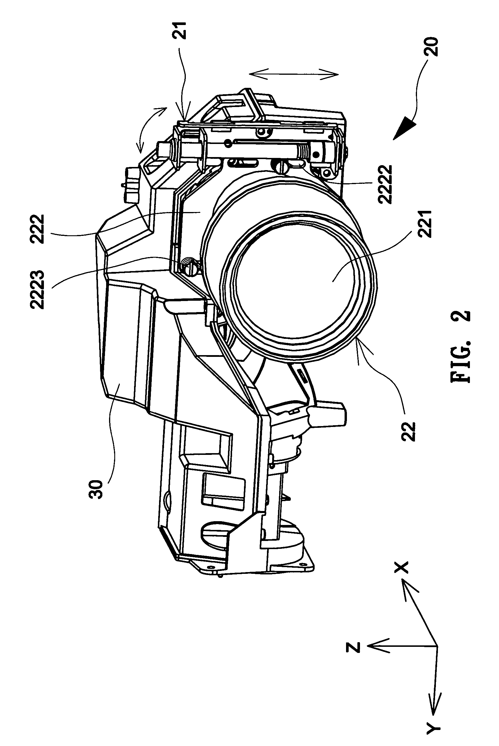
[0013]Please refer to FIG. 2. The projection lens movement-adjusting apparatus 20 according to the present invention is composed of an adjusting module 21 and a projection lens module 22. The projection lens module 22 is fixed on the adjusting module 21 by linking unit 222, and by rolling the adjusting module 21 the projection lens module 22 will be pushed forward to make a linear movement.

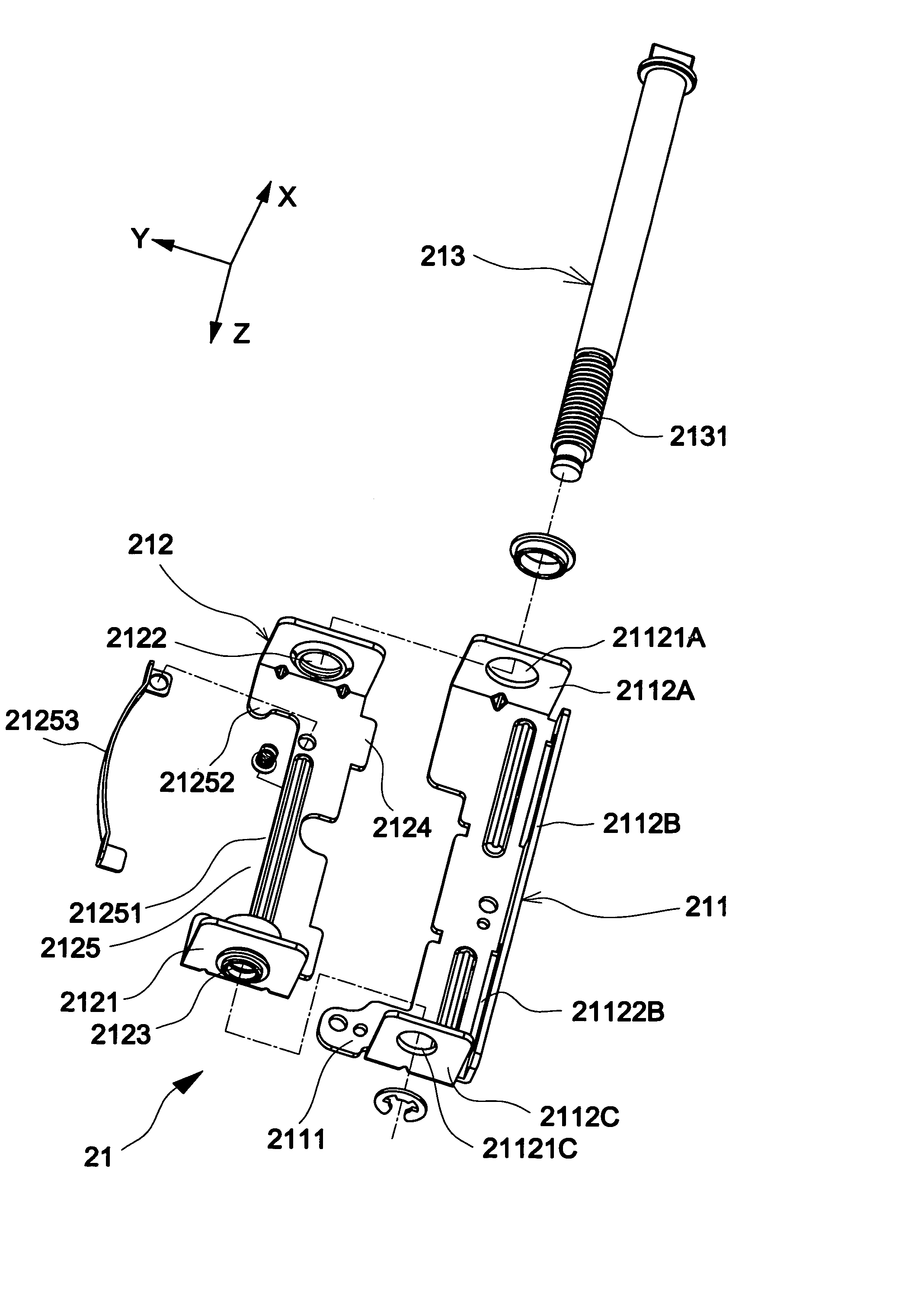
[0014]Please refer to FIG. 3. The adjusting module 21 is composed of a fixed support 211, a sliding seat 212 and an adjusting rod 213. The fixed support 211 is composed of a base 2111 and three adjacent sideboards 2112A, 2112B and 2112C disposed perpendicular to the base 2111. There are through holes 21121A, 21121C disposed on the opposite sideboards 2112A and 211C. The axial center of the through hole 21121A and 21121C are parallel to the z-axis. There is a groove 21122B parallel to the z-axis disposed on the other sideboard 2112B. The sliding seat 212 is mounted inside the fixed support 211 and ...


PUM


Abstract

A projection lens movement-adjusting apparatus comprises an adjusting module and a projection lens module. The adjusting module comprises a fixed support, an adjusting rod, a sliding seat and a fixing portion. The adjusting rod is pivoted to the fixed support. The sliding seat is mounted inside the fixed support and screwed to the adjusting rod. A fixing portion is disposed on one side of the sliding seat. The projection lens module is composed of projection lens and the linking unit fixed to one side of the projection lens, and a protruding board is on one side of the linking unit and is fixed firmly to the fixing unit and hence the projection lens module can be connected with the sliding seat.

Description

FIELD OF THE INVENTION[0001]The present invention relates to an adjusting apparatus, and more particularly to a projection lens movement-adjusting apparatus applied in a projector display apparatus.BACKGROUND OF THE INVENTION[0002]Please refer to FIG. 1, which is a lens adjusting apparatus 10 disclosed in U.S. Pat. No. 5,895,110. A fixed board 12 is disposed perpendicular to a base 11 to form a L-shape. Then a U-type supporting plate 13 is disposed on the fixed board 12, and the U-type supporting plate 13 faces upward with gaps on both sides between the-U type supporting plate and the fixed board 12 in order to form a sliding groove 131. There is a hinge 14 disposed on one upper corner of the fixed board 12. Then a projection lens module 16 is equipped on one end of the sliding unit 15 that has a screw nut 17 firmly matched to the hinge 14. The sliding unit 15 is inserted into a sliding groove 131 from the opening of the supporting unit 13, and the adjusting rod 18 passes through th...

Claims


Application Information

Patent Timeline
Patent Type & Authority Patents(United States)
IPC IPC(8): G02B7/02G03B3/00G03B21/00G03B21/14
CPCG03B21/14G03B5/00G03B21/142
Inventor LEE, CHIA-CHANGWANG, WAN-CHIANG
Owner YOUNG OPTICS
Why Eureka
Try Eureka