Vehicle detecting sensor assembly

a sensor and vehicle technology, applied in the direction of radiating element housings, instruments, measurement devices, etc., can solve the problems of adversely affected, inverse operation, impaired or tampered outward protruding horns, etc., to reduce the influence of the sensor assembly brought about by the fall of water, reduce the impact of water drop on the surface of the radome, and facilitate installation

Inactive Publication Date: 2015-05-14
OPTEX CO LTD
View PDF6 Cites 5 Cited by
  • Summary
  • Abstract
  • Description
  • Claims
  • Application Information

AI Technical Summary

Benefits of technology

[0016]According to the present invention, by selecting the shielding member in dependence on the position of installation of the sensor relative to the parking area, due to the fact that the detection range angle of the microwave can be limited and that an object, which is shorter than the arbitrary distance from the sensor assembly within the parking area can be determined as the parked vehicle, the erroneous detection resulting from the vehicle parked outside the parking area can be easily avoided. Also, since the distance of separation between the microwave module thereof and the radome, through which the microwave passes, is so disposed as to be in the vicinity of the n times the half-wave length of the microwave, it would not be adversely affected by the drops of water sticking to the surface of the radome and, hence, the influence on the sensor assembly brought about by the fall of water can be reduced as minimal as possible.
[0017]In the practice of the present invention, the sensor assembly is preferably fitted to a support body which is disposed at a position in the vicinity of the outside of the area or above the area. Accordingly, since the sensor assembly can be fixed to the support body, such as, for example, a pole disposed outside or upwardly of the parking area, by the use of a U-shaped metal piece, it becomes easy to orient the direction of fitting of the sensor assembly towards the parking area and, therefore, installation can be facilitated.
[0018]In a preferred embodiment of the present invention, a water fall shielding body for covering the radome is preferably employed to avoid sticking of drops of water, resulting from a fall of water (water fall), to a surface of the radome. In such case, because of the use of the water fall shielding member, sticking of the drops of water onto the radome surface is minimized and, hence, the influence on the sensor assembly brought about by the fall of water such as, for example, rainfall can be minimized.
[0019]The sensor assembly may be disposed in an outdoor parking space such that it is susceptible to an influence brought about a fall of water. In this case, the necessity of minimizing the influence on the sensor assembly which would be brought about by the fall of water is high. Also, the radome referred to above may be made of a resinous material and has a thickness that is chosen in consideration of the wavelength of the microwave and the dielectric constant of the resinous material so that the microwave passing through the radome may not be adversely affected. The shielding member may protrude in the direction of transmission of a microwave, and may be positioned rearwardly of the radome. In this case, since the shielding member does not protrude outwardly of the radome, the possibility may be minimized that it may be damaged or tampered unlike the conventional horn construction.

Problems solved by technology

In the system in which the horn is used to narrow the detecting area, there is the possibility that the outwardly protruding horn may be impaired or tampered.
But the AIR system is incapable of being used outdoor and, at the same time, since it is a relative detection system, it is liable to an erroneous detection because it involves a inverting phenomenon (a phenomenon in which if the object is held in a constant state for a prolonged time, it is erroneously stored as a background, resulting in a non-detection, but if the object moves, it may inversely operate as detection).
Since it is the determination based on the distance and is, therefore, an absolute detection system, no inverting phenomenon occurs, but it may be adversely affected by rainfall.

Method used


Image

  • Vehicle detecting sensor assembly
  • Vehicle detecting sensor assembly
  • Vehicle detecting sensor assembly

Examples


Embodiment Construction

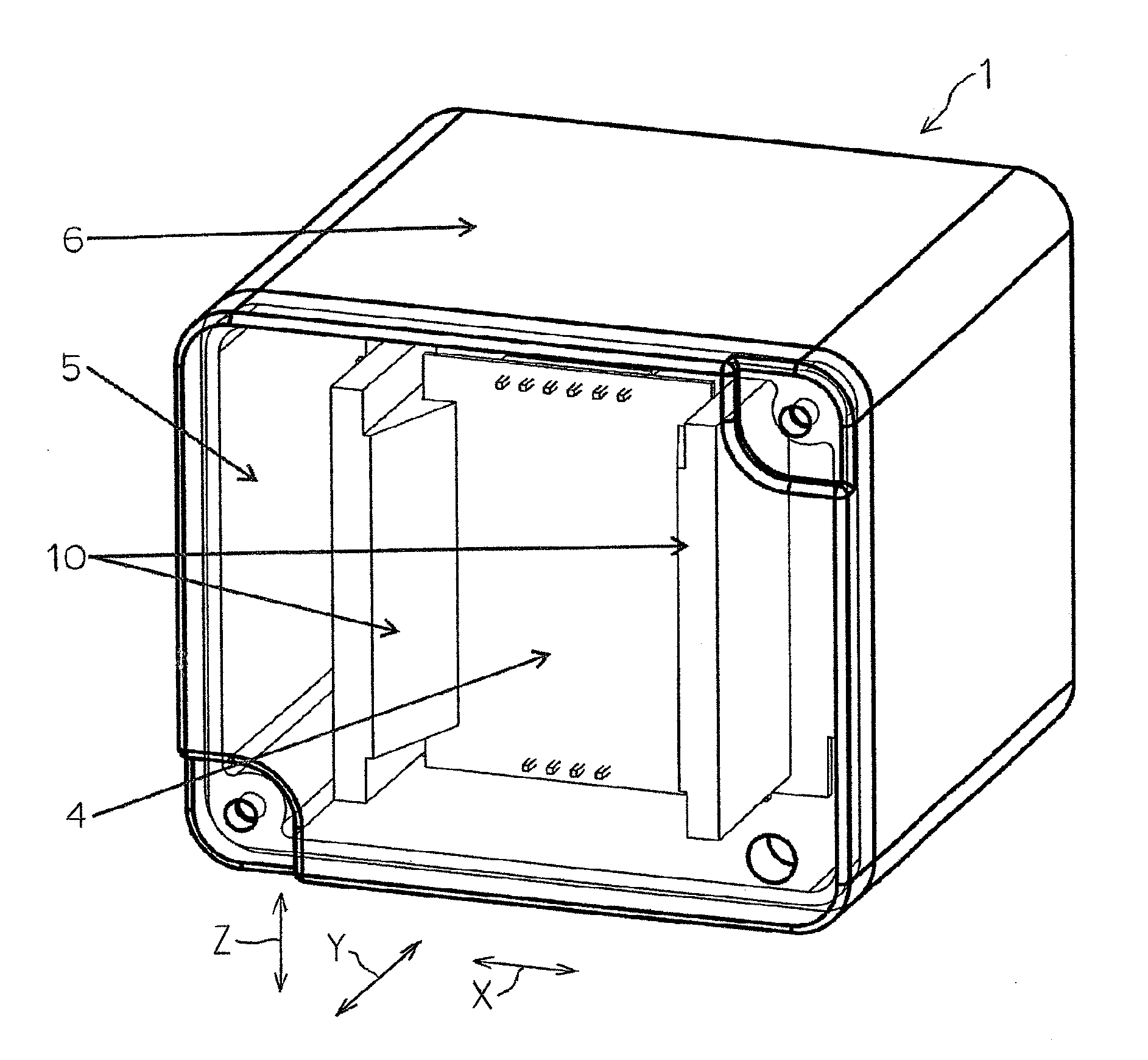
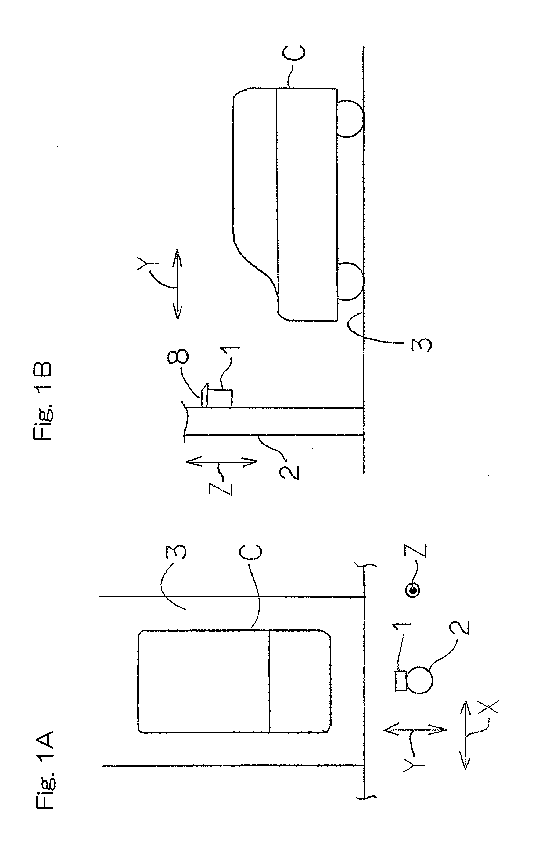
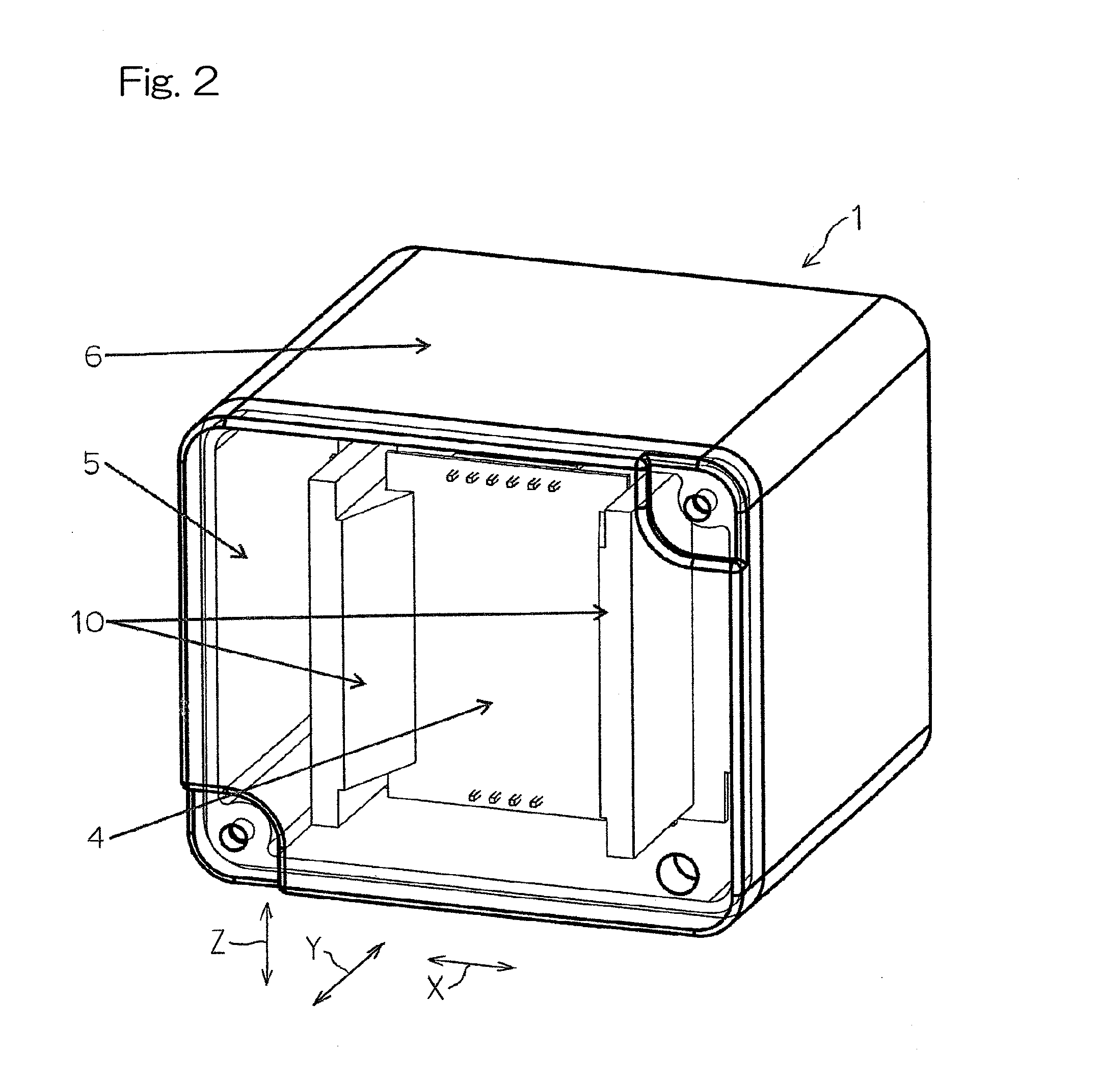
[0031]Hereinafter, a preferred embodiment of the present invention will be described in detail with particular reference to the accompanying drawings. In particular, FIG. 1A illustrates a schematic top plan view showing the manner of installation of a vehicle detecting sensor assembly 1 in accordance with the preferred embodiment of the resent invention and FIG. 1B illustrates a schematic side view of FIG. 1A. The sensor assembly 1 is of a type that is used in, for example, an outdoor parking place and is, as shown in FIG. 1A, fitted to a support body 2 such as, for example, a wall or a pole that is installed upright so as to extend in a vertical direction Z in the vicinity of an outer side of a plurality of parking areas or lots 3, where corresponding vehicles C can park. As shown in FIG. 1B, the sensor assembly 1 is disposed in the support body 2 at a heightwise position approximating to the height of the parked vehicle C so that the parked vehicle C can be detected from a longitu...


PUM


Abstract

A vehicle detecting sensor assembly (1) includes a microwave module (4) and a radome (5) for detecting the presence or absence of a parked vehicle, parked in a predetermined parking area (3), according an FMCW scheme. A shielding member (10) is provided on each of left and right sides, each of upper and lower sides or each of upper and lower and left and right sides of the module so as to protrude in a direction, conforming to the direction of transmission of a microwave, so that a detection range angle by the microwave can be varied in dependence on the position of the sensor and the size of the parking area, and a so disposed that the distance of separation between the module and the radome, through which the microwave passes, may lie in the vicinity of n times the half-wave length of the microwave.

Description

CROSS REFERENCE TO THE RELATED APPLICATION[0001]This application is based on and claims Convention priority to Japanese patent application No. 2013-233893, filed Nov. 12, 2013, the entire disclosure of which is herein incorporated by reference as a part of this application.BACKGROUND OF THE INVENTION[0002]1. Field of the Invention[0003]The present invention relates to a vehicle detecting sensor assembly for detecting the presence or absence of a vehicle in a parking area or lot by means of the FMCW scheme utilizing microwaves.[0004]2. Description of Related Art[0005]In general, as the vehicle detecting sensor assembly for detecting the presence or absence of a vehicle parked in the parking lot, an ultrasonic sensor assembly has been suggested in, for example, the patent document 1, listed below, in which an ultrasonic sensor is fitted to a ceiling of the parking lot to emit ultrasonic waves towards a floor surface of the parking lot so that based on waves reflected from the vehicle ...

Claims


Application Information

Patent Timeline
Patent Type & Authority Applications(United States)
IPC IPC(8): H01Q1/42G01S13/04
CPCG01S13/04H01Q1/42G01S7/4034G01S7/403G01S7/027
Inventor SHIRAISHI, MASANAOTAKADA, YASUHIROKAGEYAMA, NAOKIMIHARA, MITSUGU
Owner OPTEX CO LTD
Why Eureka
Try Eureka