Method of identifying a movement by quantified recursive bayesian filtering

a recursive, quantified technology, applied in the field of identifying, a movement of a human being, can solve the problems of long computing time and too slow identification of movements for video game applications

Inactive Publication Date: 2017-05-25
MAROY
View PDF5 Cites 10 Cited by
  • Summary
  • Abstract
  • Description
  • Claims
  • Application Information

AI Technical Summary

Problems solved by technology

However, all of the techniques in the article have a long computing time, mak

Method used


Image

  • Method of identifying a movement by quantified recursive bayesian filtering
  • Method of identifying a movement by quantified recursive bayesian filtering
  • Method of identifying a movement by quantified recursive bayesian filtering

Examples


first embodiment

[0158]The operation of the system 10 will now be described in reference to FIGS. 2 to 4, which illustrate an example implementation of the method for identifying the movement to be identified according to a

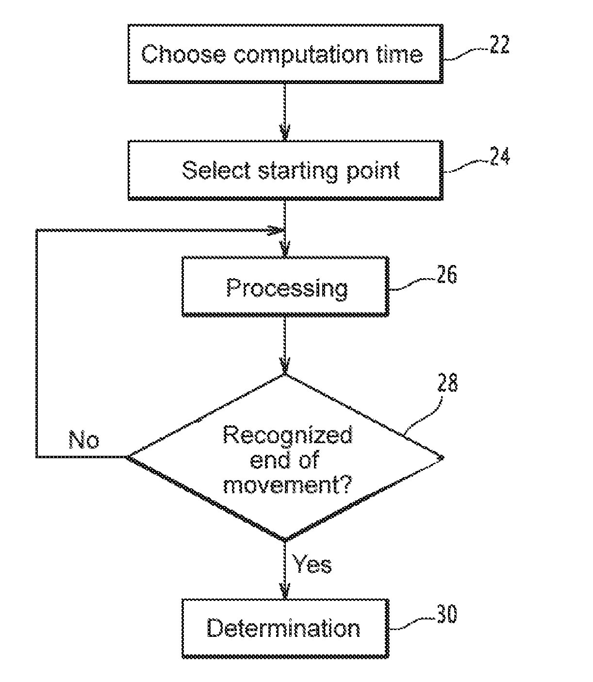
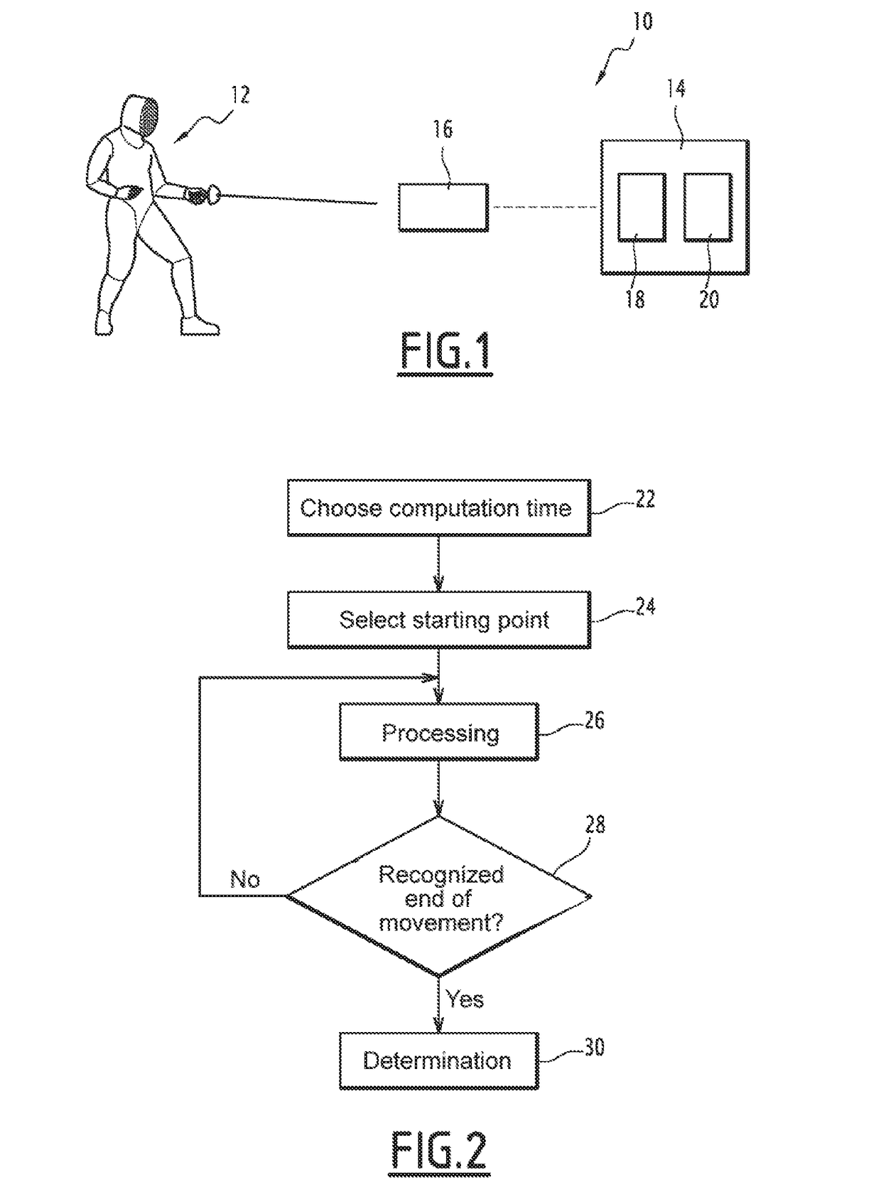
[0159]FIG. 2 more specifically shows the iterative architecture of the proposed identification method. FIG. 2 is more specifically described below.

[0160]The identification method includes a step 22 for choosing a computation time interval.

[0161]According to one embodiment, step 22 is carried out by having an operator enter a computation time interval. Alternatively, the computer 14 is able to determine the computation time interval automatically. In particular, when the computation points are replaced by averages, an excessively short computation time interval does not allow a real-time computation, while with an excessively long computation time interval, the central trend moves away from the actual shape of the movement and a movement change by the player 12 may not be detected....

second embodiment

[0238]the identification method is now described in reference to FIGS. 2 and 5.

[0239]The architecture of the flowchart of FIG. 2 is retained for the second embodiment of the identification method.

[0240]As a result, as for the first embodiment of the identification method, the identification method according to the second embodiment also comprises a step 22 for choosing a computation time interval, a step 24 for selecting a starting point, a processing step 26, a step 28 for recognizing the end of the movement by the player 12 and a step 30 for determining the reference movement(s) or the series of reference movement parts representative of the movement by the player 12. The step 22 for choosing a computation time interval and the step 28 for recognizing the end of the movement by the player 12 are identical to the preceding description. The associated features are not repeated for the description of the identification method according to the second embodiment, but also apply.

[0241]O...

third embodiment

[0256] optionally used in combination with one or several of the preceding embodiments, between all of the paths ending with a point belonging to the same reference kinematic, only the path with minimum energy is retained. Preferably, several paths are retained: at least, per reference kinematic, one path whose last point belongs to that reference kinematic. As an example, according to the second rule, if a point deduced at the end of the deducing sub-step 106 belongs to two different paths, only the path whose series of points has a minimal energy is selected. This makes it possible to reduce the number of authorized paths and thus to accelerate the computation.

[0257]Preferably, the definition of the minimum energy used in the selection sub-step 108 is the same as the definition of the minimal energy used during the implementation of the deducing sub-step 106.

[0258]According to one embodiment, the determination step 30 of the identification method according to the second embodiment...


PUM


Abstract

The invention relates to a method for analyzing a movement by a human being, the method including the following steps:
    • selecting an initial probability function,
    • processing,
    • recognizing the end of the movement to be analyzed when a criterion is verified, the processing step being iterated for as long as the criterion is not verified,
    • determining a piece of information regarding the movement to be analyzed,
      • each iteration of the processing step comprising a step for:
        • providing a set of characteristic parameters relative to the movement to be analyzed during the chosen computing time interval,
        • computing a point, the computed point belonging to a reference kinematic and making a function depending on the a posteriori conditional probability function extremal,
      • the determination step taking into account the points computed upon each iteration of the processing step.

Description

TECHNICAL FIELD OF THE INVENTION[0001]The present invention relates to a method for analyzing, and in particular identifying, a movement of a human being. The present invention also relates to a computer program product able to carry out the identification method. The present invention also relates to a recognition method implementing the identification method. The present invention also relates to a system for identifying a movement of a human being, in particular for a video game, able to carry out the movement identification method.BACKGROUND OF THE INVENTION[0002]In the video game field, peripherals intended for game consoles allowing a player to control video games without using traditional controllers are being developed. In particular, acquisition devices providing access to parameters relative to a movement by the player exist. The Wiimote controller, the Kinect peripheral, the PlayStation Move system or the Razer Hydra are examples of such acquisition devices.[0003]More spe...

Claims


Application Information

Patent Timeline
IPC IPC(8): G06K9/00G06K9/52A63F13/211A63F13/833A63F13/44A63F13/332G06F17/18A63F13/213
CPCG06K9/00342G06F17/18G06K9/52A63F13/213A63F13/833A63F2300/105A63F13/332A63F13/211A63F2300/1093A63F2300/638A63F13/44G06V40/23G06V10/85G06F18/295
Inventor MAROY
Owner MAROY
Why Eureka
Try Eureka