Method for Determining Transmission Time, Terminal, Base Station, System and Storage Medium

a synchronization signal and transmission time technology, applied in the field of communication, can solve problems such as increasing complexity of current communication, and achieve the effects of improving the synchronization accuracy between the terminal and the base station, facilitating completion of synchronization, and accurate synchronization time of the synchronization signal

Inactive Publication Date: 2017-05-25
ZTE CORP
View PDF2 Cites 22 Cited by
  • Summary
  • Abstract
  • Description
  • Claims
  • Application Information

AI Technical Summary

Benefits of technology

[0272]The embodiments of the present document provide the method for determining the transmission time of the synchronization signal, the terminal, the base station, the communication system, and the storage medium. The terminal not only receives the synchronization signal, but also acquires the time index of the synchronization signal, such that more accurate synchronization time of the synchronization signal may be obtained, and when applied to the terminal, the base station or the communication system capable of receiving a plurality of synchronization signals within a synchronization period, the terminal will determine the transmission time of each synchronization signal according to the time index of each synchronization signal, thereby solving the problem in the existing technology that a terminal, within synchronization periods, only knows within which synchronization period a synchronization signal is located, but cannot accurately learn that the synchronization signal is located in which sub-frame, micro-frame or transmission symbol. Thus, the synchronization accuracy between the terminal and the base station is improved, so as to facilitate completion of synchronization between the terminal and the base station in conjunction with two pieces of information such as a time index and a synchronization signal.

Problems solved by technology

Thus, under a communication environment where current communication is increasingly complicated, how to realize synchronization between the terminal and the base station and how to improve the synchronization accuracy between the terminal and the base station are the problems to be urgently solved in existing technologies.

Method used


Image

  • Method for Determining Transmission Time, Terminal, Base Station, System and Storage Medium
  • Method for Determining Transmission Time, Terminal, Base Station, System and Storage Medium
  • Method for Determining Transmission Time, Terminal, Base Station, System and Storage Medium

Examples


embodiment 1

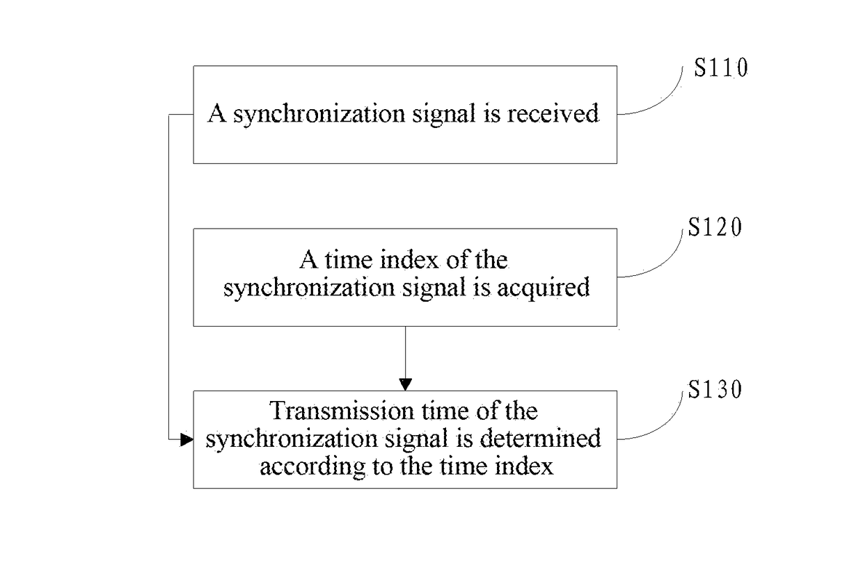
[0283]As shown in FIG. 1, this embodiment provides a method for determining a transmission time of a synchronization signal, the method including the following steps:

[0284]in step S110, a synchronization signal is received;

[0285]in step S120, a time index of the synchronization signal is acquired;

[0286]in step S130, a transmission time of the synchronization signal is determined according to the time index.

[0287]A terminal may receive at least two synchronization signals within one synchronization period; specifically, for example, a plurality of different synchronization signals is received at the same time, and a plurality of identical or different synchronization signals are received at different times. If the terminal receives at least two synchronization signals within one synchronization period, how to determine the transmission time of each synchronization signal is a problem; in this embodiment, the terminal further includes the step of acquiring time indexes corresponding t...

embodiment 2

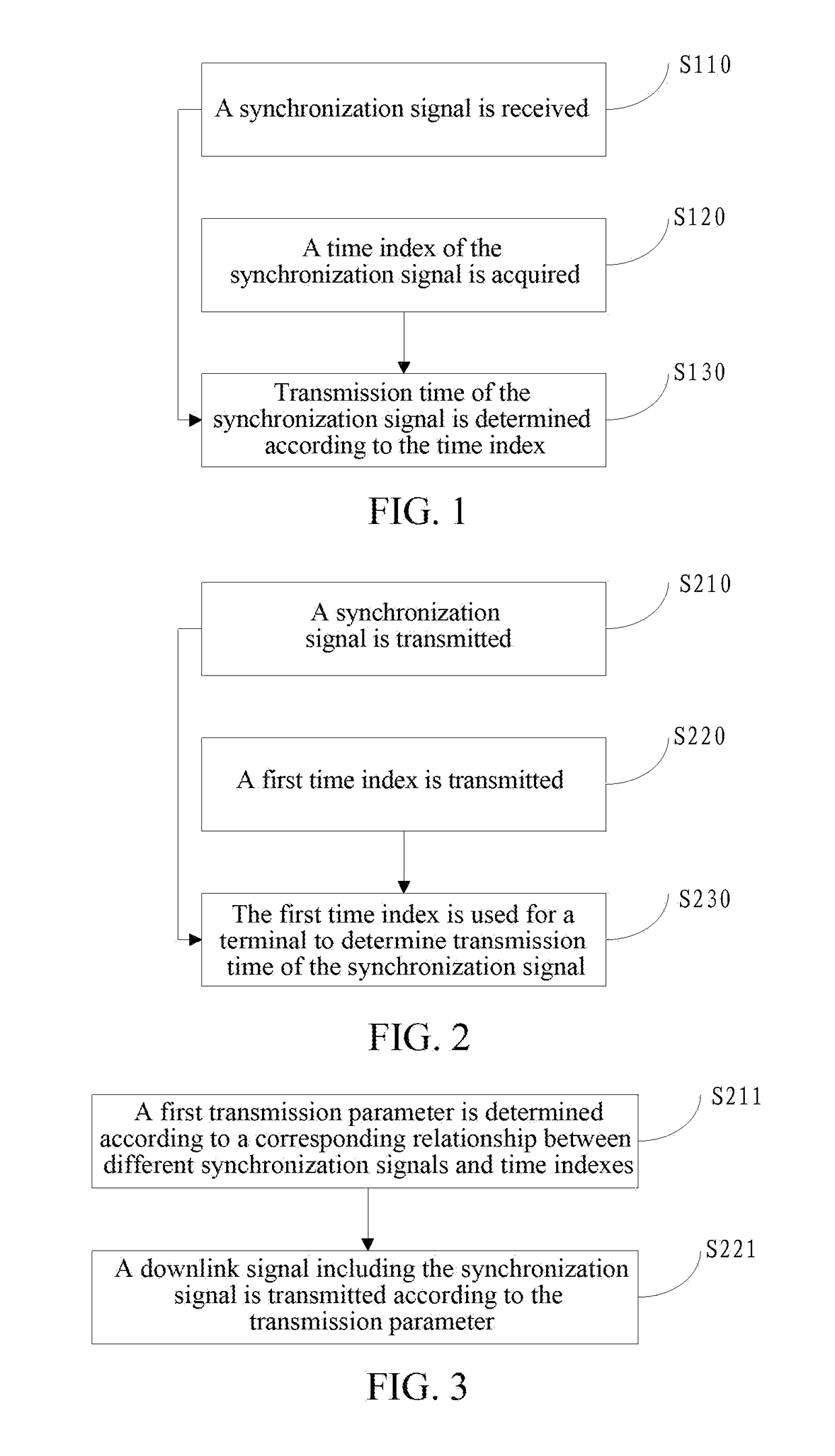
[0360]As shown in FIG. 2, this embodiment provides a method for determining a transmission time of a synchronization signal, the method including the following steps:

[0361]in step S210, the synchronization signal is transmitted;

[0362]in step S220, a first time index is transmitted;

[0363]in step S230, the first time index is used for a terminal to determine the transmission time of the synchronization signal.

[0364]When the synchronization signal is transmitted, generally a plurality of synchronization signals may be transmitted within a synchronization period; specifically, for example, a plurality of different synchronization signals are transmitted at the same time, and a plurality of identical or different synchronization signals are transmitted at different times.

[0365]A base station will also transmit the first time index in the step S220 at the same time; specifically, for example, when a synchronization signal A is transmitted, the first time index corresponding to the synchro...

embodiment 3

[0387]As shown in FIG. 3, this embodiment provides a method for determining a transmission time of a synchronization signal, herein the method includes the following steps:

[0388]in step S211, a transmission parameter is determined according to a corresponding relationship between different synchronization signals and time indexes;

[0389]in step S221, a downlink signal including the synchronization signal is transmitted according to the transmission parameter,

[0390]herein the transmission parameter is used for representing the time index; and

[0391]the time index is a time index for a terminal to determine the transmission time of the synchronization signal.

[0392]The time index may, at least, includes the second time index, the third time index and the fourth time index.

[0393]When the time index is the second time index, two optional modes are provided to realize representing of the second time index as follows.

[0394]Mode 1: the synchronization signal includes a main synchronization si...


PUM


Abstract

The present document discloses a method for determining a transmission time of a synchronization signal, a terminal, a base station, and a communication system. The method for determining the transmission time of the synchronization signal includes: receiving the synchronization signal; acquiring a time index of the synchronization signal; and determining the transmission time of the synchronization signal according to the time index. The present document also discloses a computer storage medium.

Description

TECHNICAL FIELD[0001]The present document relates to a synchronization technology in the field of communications, and in particular to a method for determining a transmission time of a synchronization signal, a terminal, a base station, a system, and a storage medium.BACKGROUND OF THE RELATED ART[0002]In a communication process, in order to make it convenient for a terminal to access a network, via a base station, for information interaction with other terminals or network devices, the terminal needs to synchronize with the base station. The synchronization includes time synchronization and frequency synchronization. Besides, the terminal probably needs to detect a discovery signal to obtain optimal beam index information. However, with the development of a communication technology, there are more and more signals and signalings in interaction between the terminal and the base station, and requirements for synchronization accuracy are increasingly high. Thus, under a communication e...

Claims


Application Information

Patent Timeline
Patent Type & Authority Applications(United States)
IPC IPC(8): H04W56/00H04W48/16
CPCH04W48/16H04W56/001H04W56/0015H04L27/2662H04L27/2655H04L27/2656H04L27/2671H04L27/2673H04W56/00
Inventor LI, CHUNXUGUO, SENBAOYU, GUANGHUI
Owner ZTE CORP
Why Eureka
Try Eureka