Base station transceiver to radio network controller synchronization filtering function

a technology of synchronization function and base station, applied in the field of telecommunications, can solve the problems of large time error, inability to account for delays that arise, and inability to know, so as to achieve accurate synchronization time, accurately synchronize time, and accurately hone in on proper delay

Inactive Publication Date: 2006-06-27
RPX CORP +1
View PDF12 Cites 24 Cited by
  • Summary
  • Abstract
  • Description
  • Claims
  • Application Information

AI Technical Summary

Benefits of technology

[0010]The present invention provides a method of accurately synchronizing the time between the components of a wireless telecommunications system.
[0011]The present invention also provides a method of accurately synchronizing the time between the components of a wireless telecommunications system that also filters out undesirable synchronization data.
[0012]The above and other features and advantages of the invention are achieved by initiating several time synchronization passes between clock slave components and a clock master component in a wireless telecommunications system. For every pass, each clock slave component generates and transmits a first timing cell to the clock master. The first timing cell contains a transmission time based on the clock slave component's clock. Upon receipt of the first timing cell, the clock master generates and transmits to the clock slave component a second timing cell containing the time the clock master received the first timing cell and the time the master transmitted the second timing cell. Upon receipt of the second timing cell, the clock slave component will obtain its reception time and calculate a transmission delay based on the reception time and the timing information contained in the timing cells. Each clock slave component utilizes a sliding window filtering function to drop information from a synchronization pass that may have undesirable data due to processing and other delays. The filtering function will also restart the synchronization process whenever a calculated transmission delay is smaller than the best transmission delay. This allows the process to accurately hone in on the proper delay experienced between each clock slave component and the clock master. After timing information from a predetermined number of time synchronization passes has been obtained, each clock slave component uses an average transmission delay to synchronize its time to the clock master time.

Problems solved by technology

This is a problem because the components of the system 100, with the exception of the clock master (typically the RNC 120 or an external component connected to the RNC 120), do not know what the actual system time is and, more importantly, they do not know the time of the other components within the system 100.
For example, this technique does not account for delays that arise between the time the reference time was created by the clock master and the time the other components (i.e., clock slaves) within the system receive the time reference.
Often times, however, this time error is very large because of processing delays experienced by the clock master or transmission delays.
Moreover, the transmission delays experienced by each component may vary, which means that each component will have a different time error causing additional problems within the system.

Method used


Image

  • Base station transceiver to radio network controller synchronization filtering function
  • Base station transceiver to radio network controller synchronization filtering function
  • Base station transceiver to radio network controller synchronization filtering function

Examples


Embodiment Construction

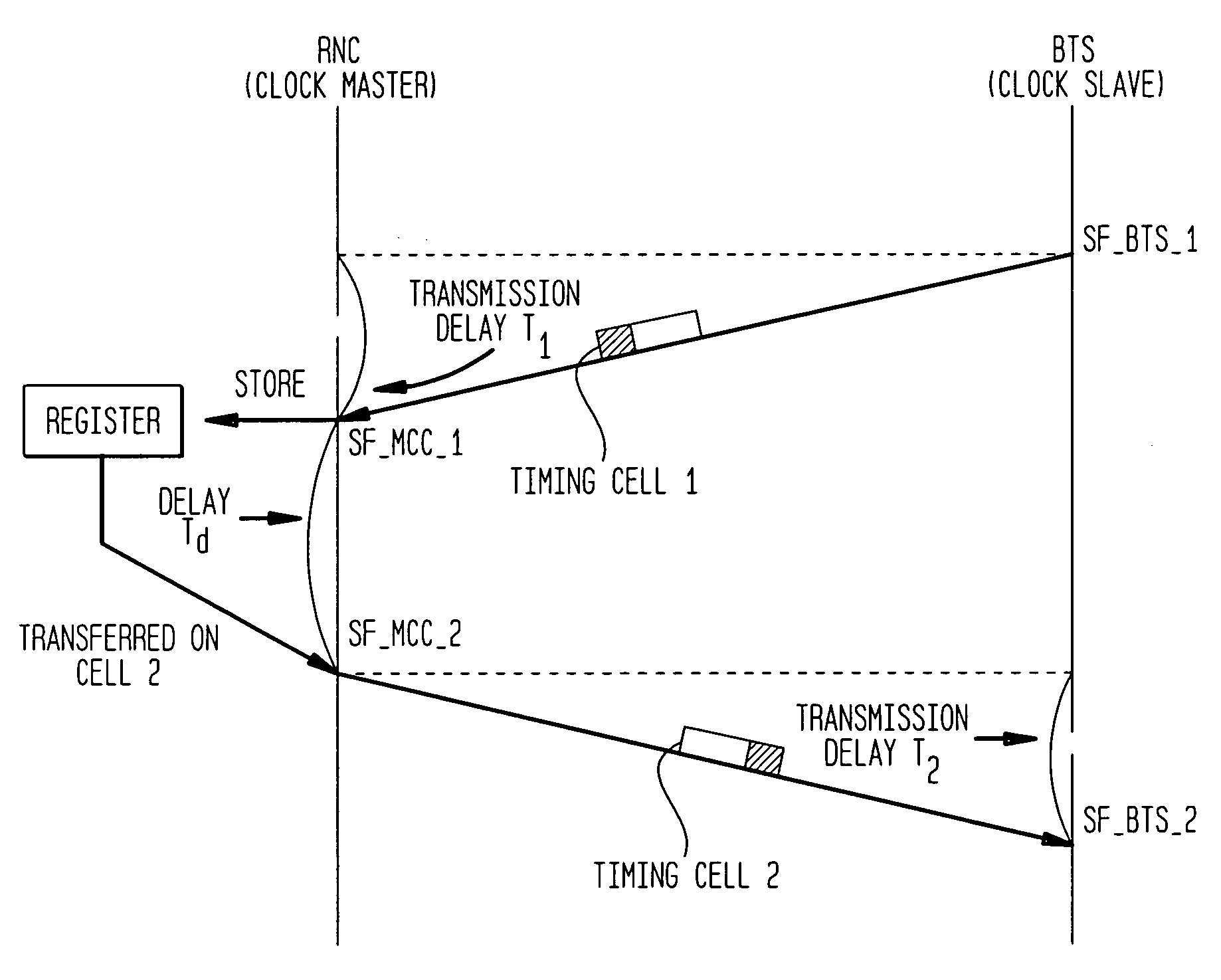
[0018]Another way to perform time synchronization would be to accumulate timing data samples from several time synchronization communications between the system clock master and the other components within the system (i.e., the clock slave components). Each data sample should represent a transmission delay experienced by the clock master and a slave component during the communication with each other. For example, when the clock master sends a message to a clock slave, the message is not received by the slave until after a transmission delay. If the delay where known, than the delay could be added to the transmitted clock master time to calculate the current clock master time. This would improve the accuracy of the time synchronization process. The transmission delay may vary from communication to communication. Thus, to get a better judge of the typical transmission delay experienced between the clock master and a clock slave, several samples are used and an average transmission del...


PUM


Abstract

A method for synchronizing communications in a wireless communications network wherein time synchronization is performed between a clock master and a clock slave. To achieve synchronization between the clock master and the clock slave, several time synchronization passes are initiated by the clock slave to the clock master. For every pass, each clock slave component generates and transmits a first timing cell containing a transmission time based on the clock slave's component clock, to the clock master. Upon receipt of the first timing cell, the clock master generates and transmits to the clock slave component a second timing cell containing the time the clock master received the first timing cell and the time the clock master transmitted the second timing cell. Upon receipt of the second timing cell, the clock slave component will obtain its reception time and calculate a transmission delay based on the reception time and the timing information contained in the timing cells.

Description

BACKGROUND OF THE INVENTION[0001]1. Field of the Invention[0002]The present invention relates generally to the field of telecommunications and, more particularly, to an accurate time synchronization method having a filtering function for a wireless telecommunications system.[0003]2. Description of the Related Art[0004]FIG. 1 illustrates a schematic diagram of a portion of a typical wireless telecommunications system 100. The system 100 provides wireless communication service to a number of wireless terminals 101-1, 101-2, 101-3 that are situated within a graphical region. The heart of a typical wireless telecommunications system 100 is the Radio Network Controller (RNC) 120, which may also be known as a Mobile Switching Center (MSC) or Mobile Telephone Switching Office (MTSO). Typically, the RNC 120 is connected to a plurality of base station transceivers 103-1, 103-2, 103-3, 103-4, 103-5 that are dispersed throughout the geographic area serviced by the system 100 and to local-offic...

Claims


Application Information

Patent Timeline
Patent Type & Authority Patents(United States)
IPC IPC(8): H04L7/00H04B7/26H04Q7/30
CPCH04J3/0682H04B7/269H04J3/0667
Inventor STICHTER, ALLEN W.
Owner RPX CORP
Why Eureka
Try Eureka