Cushion

a cushion and cushioning technology, applied in the field of cushions, can solve the problems of poor posture, unrestricted flow of fluid, and pressure on the lower spine, and achieve the effect of easy inflated or deflated, great flexibility of control for the user

Active Publication Date: 2017-06-01
SEATING DIRECT INT
View PDF5 Cites 6 Cited by
  • Summary
  • Abstract
  • Description
  • Claims
  • Application Information

AI Technical Summary

Benefits of technology

[0055]The compressible pad may comprise a solid foam, such as a polyurethane foam, which may be an open cell foam or a closed cell foam. The advantage of including a compressible pad is that further support is created for the user due to the resilience of the foam, in addition to the support already provided by the internal fluid pressure. An open cell foam is advantageous in that it can expand and contract depending upon the pressure inside the cushion and therefore allows greater flexibility of control for the user.
[0056]In some embodiments of the invention, it is advantageous if the cushion further comprises a pressure release valve and / or a pump. If the fluid to fill the chambers of the cushion is a gas (e.g. air), the cushion of the present invention may further comprise an air pump and air pressure release valve. This is advantageous as the cushion may be easily inflated or deflated to meet the changing requirements of a single user, or the requirements of different users. The pump may be manually operated or motorised. A pressure release valve (e.g. air pressure release valve) is advantageous because the level of (air) inflation of the cushion may be controlled to suit the individual needs of the user. Generally, inflation of the cushion relies on the elasticity of the upper and lower layers of the cushion and, if present, the expansion of the compressible pad.

Problems solved by technology

Incorrectly designed seating can cause poor posture, which can lead to pressure on the lower spine.
However, unrestricted flow of fluid can be problematic, as too much movement of the fluid under the weight of the user can lead to rapid and uneven fluid distribution, resulting in poor support for the user.
However, each break in the seal creates a weak point and increases the likelihood of a leak from the cushion under the fluid pressure within the cushion and under the weight of the user.
Any leak in the seal is a particular problem where the cushion is built-in to an expensive chair.
Further, the weight of the user may partially close off an aperture, again leading to uneven fluid movement within the cushion and poor support for the user.

Method used


Image

  • Cushion
  • Cushion
  • Cushion

Examples


Embodiment Construction

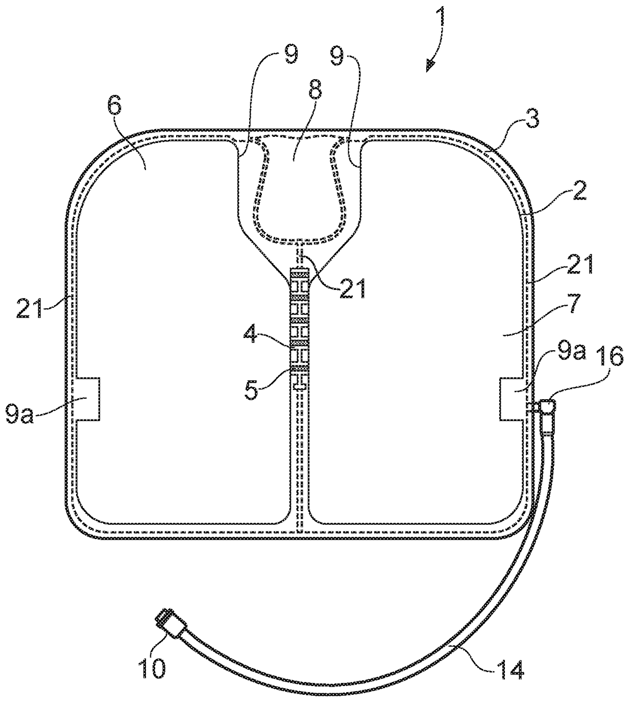
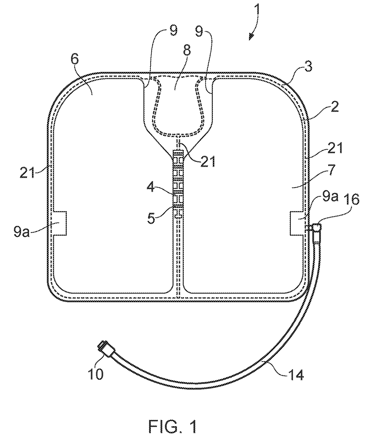
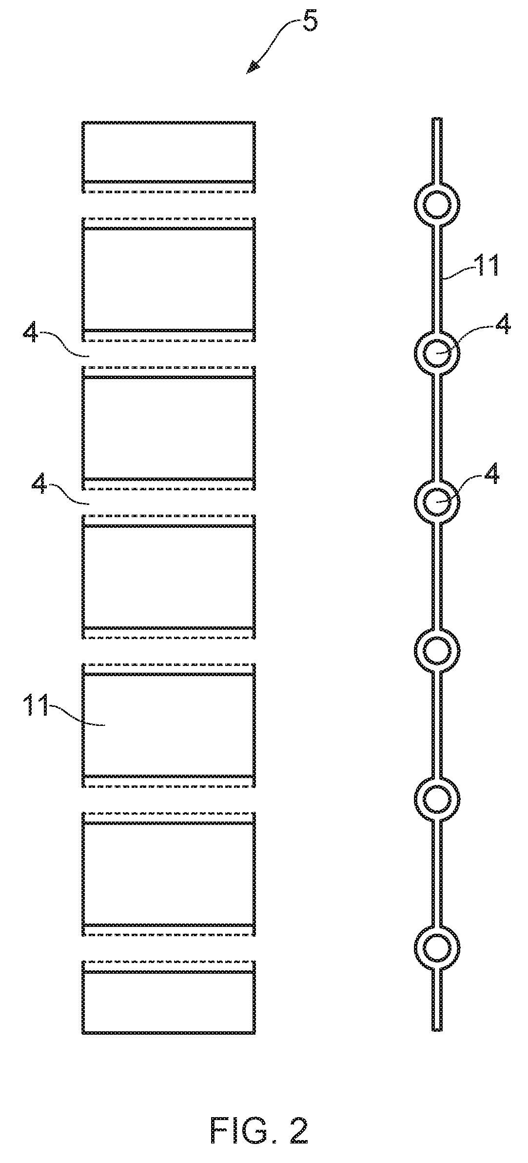
[0076]FIG. 1 shows a cushion 1 of the present invention. The cushion 1 is intended to be used in the seat of a chair, and includes a coccyx cut-out region 8 to accommodate the base of the spine for user comfort and a first fluid fillable chamber 6 and a second fluid fillable chamber 7, separated by the pressure distributing unit 5. The use of two chambers 6,7 with a pressure distributing unit 5 allows distribution of fluid at an optimum and controlled rate around the cushion, generally producing an even pressure on both sides of the cushion thereby providing even support for the user. The pressure distributing unit 5 has fluid conduits 4 to allow fluid to flow between the chambers 6, 7. In the case of the cushion illustrated in FIG. 1, air is the fluid that fills the two chambers 6, 7 of the cushion 1, the pressure distributing unit 5 allowing controlled flow and generally equalisation of pressure between the two chambers 6, 7.

[0077]The cushion 1 comprises a compression pad 9 of a s...


PUM


Abstract

A fluid-fillable cushion comprises upper and lower layers, a first chamber and a second chamber and a discrete pressure distributing unit situated between the upper and lower layers, said pressure distributing unit providing a fluid connection between at least the first chamber and the second chamber. Such a cushion reduces leaks and allows controlled pressure equalisation between the chambers. Also disclosed is a process for making such cushions and seating products comprising such cushions.

Description

FIELD OF THE INVENTION[0001]The present invention relates to cushions, in particular to fluid-fillable cushions and parts thereof. The present invention also relates to processes for making such cushions and to seating products comprising such cushions.DESCRIPTION OF THE RELATED ART[0002]Many people suffer from lower back pain and require some form of postural support to help alleviate their discomfort. Incorrectly designed seating can cause poor posture, which can lead to pressure on the lower spine. The problem is exacerbated by today's often sedentary lifestyle.[0003]Good ergonomic seating can reduce the risk of stress and injury to muscles and joints, encouraging movement, variety and flexibility, and providing long-term comfort and improved back health.[0004]US-A-2011 / 0025111 describes a chair or seat comprising one or more self-inflatable devices inserted within the chair or seat. Each inflatable device comprises a flexible, open celled foam filled single bladder connected to ...

Claims


Application Information

Patent Timeline
Patent Type & Authority Applications(United States)
IPC IPC(8): A47C7/02A47C7/18A47C7/14
CPCA47C7/021A47C7/18A47C7/14A47C27/10A47C7/142
Inventor JONES, SIMON RUSSELL
Owner SEATING DIRECT INT
Why Eureka
Try Eureka