Irrigation pipe

a technology of irrigation pipes and pipes, applied in mechanical equipment, transportation and packaging, valve types, etc., can solve the problems of substantial variation in the shape and diameter of the pipe along its length, requiring a relatively tedious draining process, and requiring a large amount of water. to achieve the effect of improving control flexibility

Active Publication Date: 2013-01-08
NETAFIM LTD
View PDF18 Cites 15 Cited by
  • Summary
  • Abstract
  • Description
  • Claims
  • Application Information

AI Technical Summary

Benefits of technology

[0016]An aspect of some embodiment of the invention relates to providing an irrigation pipe comprising at least one integrated bipolar emitter. An irrigation pipe comprising an integrated bipolar emitter provides enhanced flexibility in controlling water discharged from an irrigation pipe by controlling inlet-pressure to the pipe.
[0017]An aspect of some embodiments of the invention relates to providing a “self emptying” irrigation pipe comprising a plurality of non-return emitters and at least one emitter, hereinafter referred to as a “free-flow” emitter, that has a discharge-pressure threshold substantially equal to zero and is not a non-return emitter. Free-flow emitters discharge water from an irrigation pipe for substantially all positive water pressures inside the pipe and enable air to enter the pipe when the pipe is being emptied. As a result, the pipe readily self empties of liquid when water to the pipe is shut off and does not develop an internal vacuum that collapses the pipe as the water leaves.

Problems solved by technology

However, integrated emitters in an irrigation pipe are not necessarily the same and equidistant from each other.
Whereas irrigation pipes configured to specific terrains and conditions for which they are to be used are beneficial, irrigation requirements, even over a same terrain, generally change over time, as, for example, crops in a field or terraced garden mature and / or their density in the field or garden changes A given configuration of emitters, even when tailored to meet the needs of a particular terrain and irrigation application can often not meet needs or the terrain and application as the needs change over a growing season.
As a result, storing the pipe after use or moving the pipe from one venue to another can require a relatively tedious draining process If water is drained from a far end of the pipe, for example from an end far from a water source to which the pipe is coupled, as the water drains, vacuum is created in the pipe that causes the pipe to collapse and fold in on itself.
When the pipe collapses, not only is there a tendency for the pipe walls and emitters in the pipe to sustain damage but the collapse is not uniform, causing substantial variation in the shape and diameter of the pipe along its length.
If the pipe is rolled up onto a spool, as is often the case after use during a growing season or in order to move the pipe from one field to another, “winding” of the pipe onto the spool is not uniform and tends to be tangled.
Subsequently, when the irrigation pipe is unrolled from the spool, the non-uniform winding and tangles tend to make it difficult to unroll and lay the pipe evenly on the ground and / or tend to cause the pipe to “catch” and get caught on the spool during unrolling.
If the pipe is unrolled by tractor, the jumbled winding and tangles generally make the task tedious and time consuming and if the pipe catches, can result in the pipe tearing or being otherwise damaged

Method used


Image

  • Irrigation pipe
  • Irrigation pipe
  • Irrigation pipe

Examples


Embodiment Construction

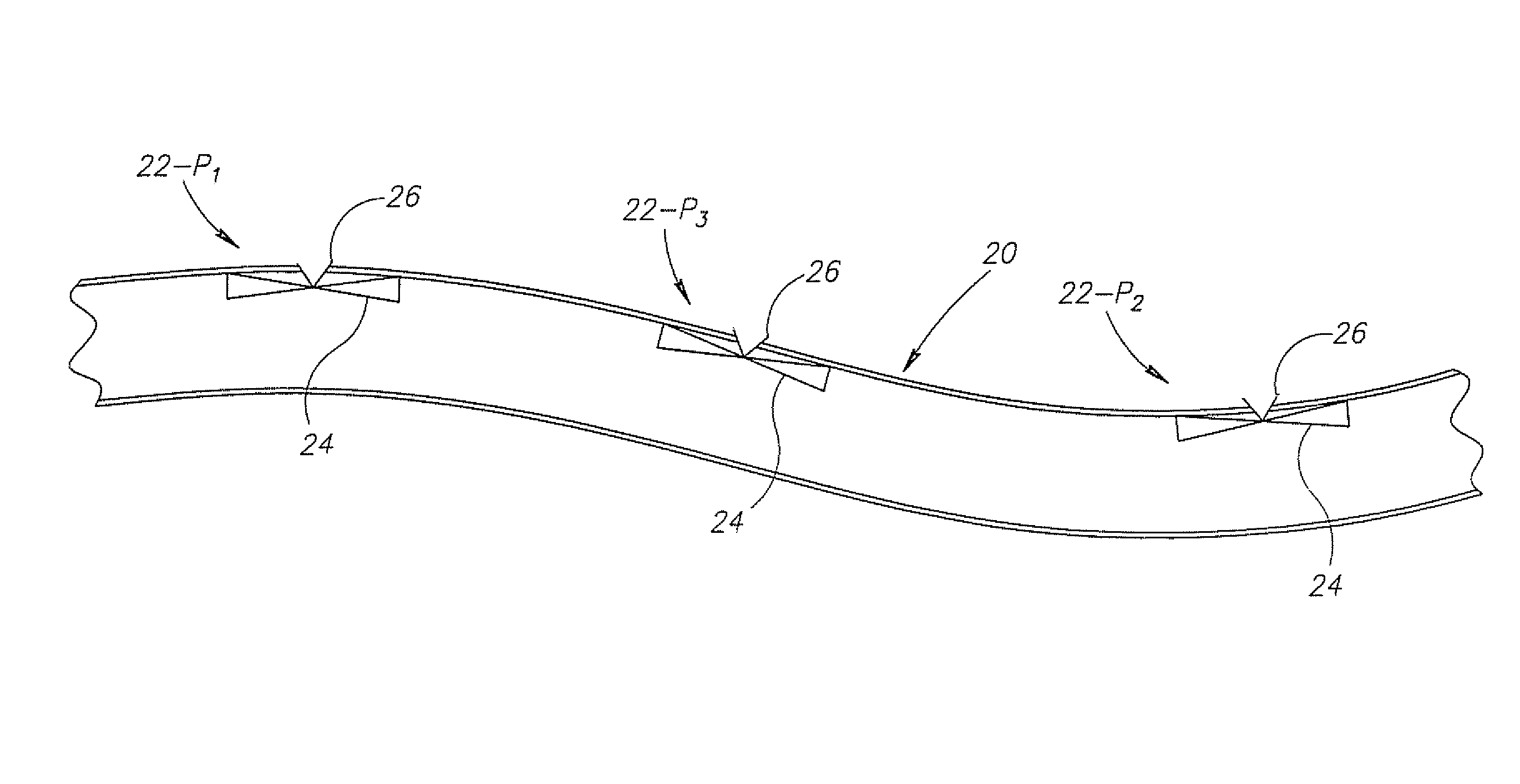
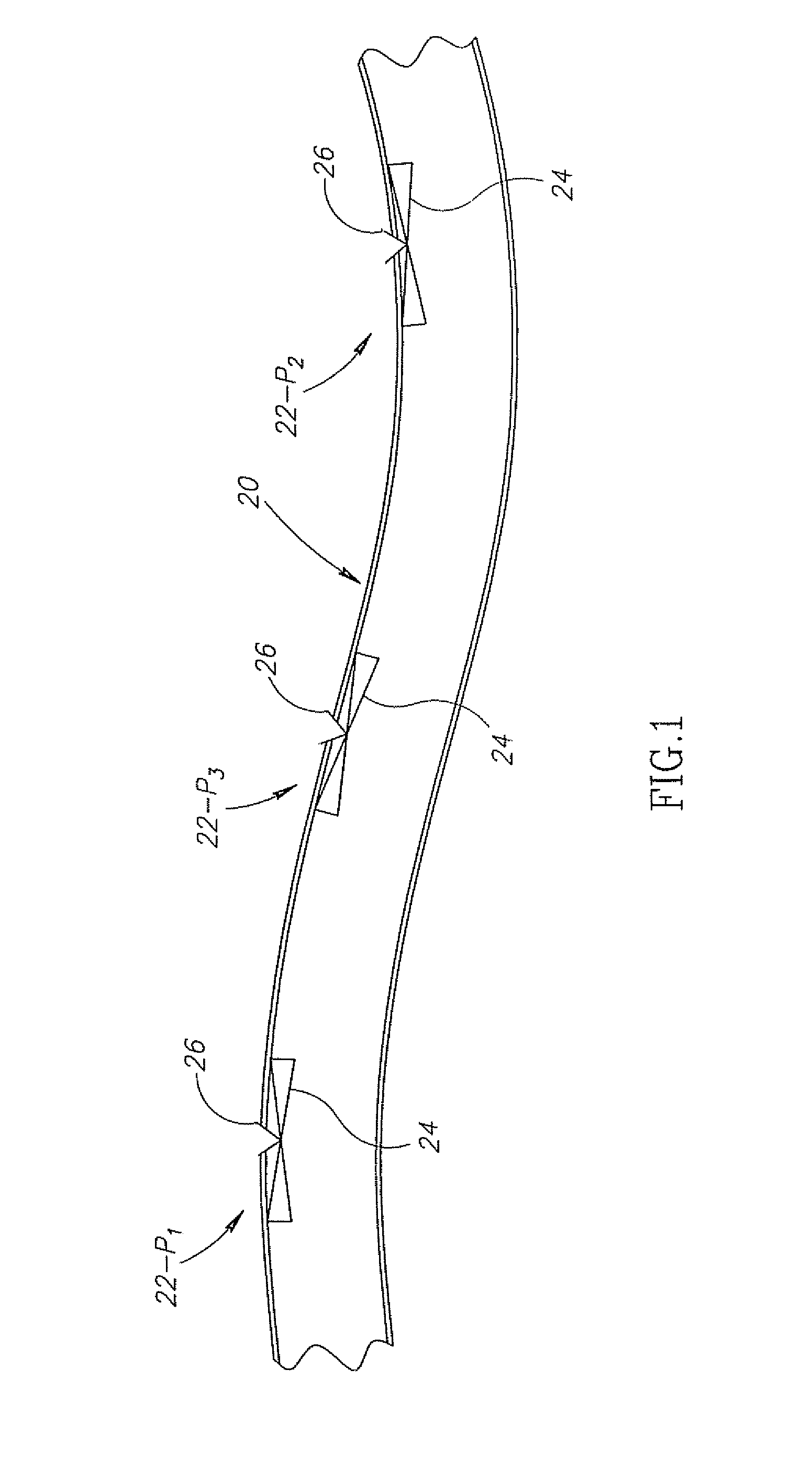
[0040]FIG. 1 schematically shows a portion of an irrigation pipe 20 having an internal lumen or cavity and comprising a predetermined configuration of a plurality of integrated emitters having different discharge-pressure thresholds, in accordance with an embodiment of the invention.

[0041]Integrated emitters in pipe 20 are labeled by an alphanumeric designation comprising the number 22 followed by a dash and an indexed letter “Pi” that indicates their respective discharge-pressure thresholds. Emitters characterized by discharge pressures Pi having a same value for the index i have same discharge-pressure thresholds and emitters characterized by pressures Pi having different index have different discharge-pressure thresholds. The emitters are referred to generically by the number 22 and are, for example, referenced by the number 22 when discussing features shared by all the emitters. In accordance with an embodiment of the invention, at least two emitters mounted to an irrigation pip...


PUM


Abstract

An irrigation pipe comprising: at least one first integrated emitter characterized by a first discharge-pressure threshold; at least one second integrated emitter characterized by a second discharge-pressure threshold different from the first discharge-pressure threshold threshold; wherein, the at least one first and at least one second integrated emitters are positioned along the pipe in accordance with a predetermined configuration.

Description

CROSS REFERENCE TO RELATED APPLICATIONS[0001]This application claims priority under 35 U.S.C. 119(a) from Israeli Application 177552, filed on Aug. 17, 2006. The entire disclosure of this application is incorporated herein by reference,FIELD OF THE INVENTION[0002]The invention relates to irrigation pipes, in particular irrigation pipes installed with a plurality of emittersBACKGROUND OF THE INVENTION[0003]Irrigation systems that deliver water, often containing plant nutrients, pesticides and / or medications, to plants via networks of irrigation pipes are very well known. In many such irrigation networks, water from the pipes is delivered to the plants by “emitters” or “drippers”, hereinafter generically referred to as emitters, that are installed on or “integrated” inside the irrigation pipes Emitters that are integrated inside an irrigation pipe are conventionally referred to as “integrated” emitters. Generally, the integrated emitters in a given irrigation pipe are equidistant from...

Claims


Application Information

Patent Timeline
Patent Type & Authority Patents(United States)
IPC IPC(8): B05B15/00B05B1/14A62C37/20F16K15/00
CPCA01G25/023A01G25/02Y10T137/7866B05B1/20
Inventor KEREN, RON
Owner NETAFIM LTD
Why Eureka
Try Eureka