Combined economizer and mixer for air handling unit

a technology of air handling unit and mixer, which is applied in the direction of ducting arrangement, lighting and heating apparatus, heating types, etc., can solve the problems of not being able to complete the mixing of the separate air streams within the mixing box, consuming a large amount of energy, and typically some amount of temperature stratification of the airstream, so as to reduce the risk of affecting the quality of the air. , the effect of reducing the risk of affecting the quality of the air

Active Publication Date: 2017-06-01
BLENDER PROD
View PDF9 Cites 2 Cited by
  • Summary
  • Abstract
  • Description
  • Claims
  • Application Information

AI Technical Summary

Benefits of technology

[0018]According to yet another aspect of the invention, automatic means are provided for controlling the position of the cover plate with respect to the front face of the device. This control can be achieved by several different actuators or motors which can effectively and incrementally shift the cover plate with respect to the front face of the device to which it is mounted.
[0019]According to another aspect of the invention, it may be considered a mixing device that mitigates temperature stratification by creation of turbulent air flow and is especially adapted for mounting within the mixing box of an air handling unit. According to this aspect, the mixing device does not replace the return air and outdoor air dampers, said dampers remaining installed. Accordingly, this aspect of the invention may be considered a sub- combination embodiment as compared to the first mentioned embodiment which provides both mixing and damper control functions. Another feature that may be associated with this aspect of the invention is the use of static mixing plates secured to selected edges of the ribs in lieu of providing a cover plate to control air flow rates and additional mixing. More specifically, these static mixing plates, for example, may be secured to the downstream edges of the ribs or may be attached adjacent to the downstream edges of the ribs. These static mixing plates may be sized and angled with respect to the direction of airflow to influence both airflow rates and additional mixing of the airflow. One advantage of this embodiment is that the existing damper control may be maintained, thereby minimizing structural changes to the mixing box of an air handling unit. Accordingly, the mixing device of this embodiment may be installed directly within the mixing box without any other structural changes being made to the damper controls or mixing box.
[0020]According to one aspect of the invention, the construction of the ribs and / or the type of material used to make the ribs can be modified to mitigate problems resulting from condensation in the mixing box. The plurality of the ribs as described herein create channels that separate OA and RA into vertical alternating “slices” of air. These separate slices of air as between the OA and RA will have different temperatures and (except of course when RA and OA have the same temperatures), and the temperature differential creates the opportunity for one airstream of colder temperature to “cool” the corresponding rib to potentially create condensation on the opposite side of the rib which carries an airstream of warmer more humid air. This condensation is undesirable and if left to form and coalesce, would flow and pool in the bottom of the mixer and the mixing box compartment of the air handling unit. The pooled condensation can cause rust and / or mold to form which can negatively impact the quality of the air in the building. One solution is for the ribs to incorporate longitudinal channels or “gutters” to collect coalesced condensation and thereby channel the moisture to a floor drain to prevent pooling of the water in the mixing box. Another solution is to thermally insulate the ribs to prevent heat transfer and therefore prevent the colder temperature airstream from cooling the opposite side of the rib containing the warmer and more humid air. One example of an insulated rib is a construction in which the rib has a double wall or double layer with an air gap between the layers. The air gap may alternatively be filled with an insulating material such as a foam or other material with low heat transfer coefficient properties. The ribs maybe constructed of a material that also has low heat transfer properties such as a plastic or corrugated plastic sheeting material.

Problems solved by technology

Depending upon the size of the building, there may be multiple air handling units required, and a substantial amount of energy may be consumed in providing the needed environmental control within the buildings.
One problem associated with airflow entering an air handling unit is that there is typically some amount of temperature stratification of the airstream.
When return air and outdoor air simultaneously enter an air handling unit, there is some inherent temperature stratification because the return air and outdoor air are two separate air streams at different respective temperatures, and there cannot be complete mixing of the separate air streams within the mixing box.
There are a number problems associated with temperature stratification.
Temperature stratification can damage cooling coils when portions of the airstream are at unacceptably cold temperatures, can cause nuisance system shutdowns because of temperature measurements that only measure a portion of the airstream, and can cause generally inefficient control system performance because air temperature and humidity measurements are not capable of accurately measuring these parameters due to the different temperature and humidity conditions found within the stratified airstream at any particular time.
Despite the number of different air mixers or air blenders which may be available, one general drawback is that these devices create a pressure drop as the airstream passes through the devices, which increases the load on the air handler fan to keep an adequate flow of air moving through the unit.
Another problem associated with most air handling units is that they fail to allow airflow to maintain sufficient velocity through the dampers located at the entrance of the mixing box.

Method used


Image

  • Combined economizer and mixer for air handling unit
  • Combined economizer and mixer for air handling unit
  • Combined economizer and mixer for air handling unit

Examples


Embodiment Construction

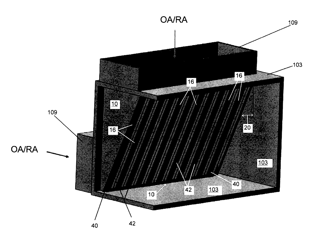
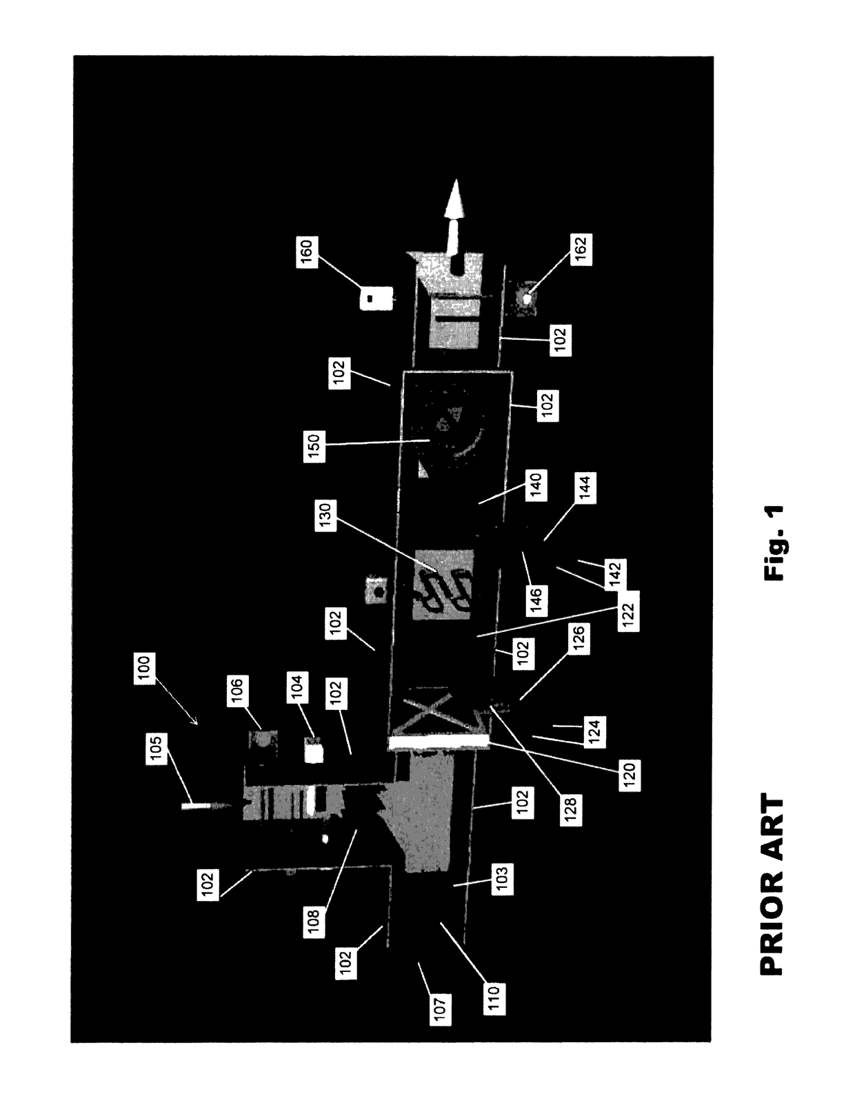
[0057]Referring to FIG. 1, a prior art and exemplary air handling unit 100 is illustrated. The purpose of this illustration is to provide background as to the particular application of the invention, and further to describe the invention in combination with an air handling unit. Components of the unit 100 are housed within a series of ducts 102. There are two inlets or entrances to the air handling unit, namely, a return air duct 105 and an outdoor air duct 107. The directional arrows are provided noting the general direction of airflow and also denoting the respective ducts. Airflow for these ducts intersects or coincides within a mixing box 103. Within the return air duct 105, one or more sensors can be provided, such as a temperature sensor 104, a humidity sensor 106, and others. Temperature and humidity are measured at this location, and may be input to an air handler controller (not shown) in order to determine the degree to which this airstream must be conditioned. A return ai...


PUM


Abstract

An air mixing device mitigates temperature stratification between two incoming air streams by creation of turbulent airflow through an arrangement of channels in the device. The device also provides selective passage of air for incoming airstreams to achieve functionality for damper control typically associated with separate inlet dampers. Static mixing plates may be employed to affect desired mixing through the device. A method provides for selectively controlled airflow through the device so effective mixing occurs along with an economizer function to control separate airstreams such as outside air and return air. Existing dampers may be integrated with the air mixing device to control airflow in which flow of one airstream through the device increases as the flow of the other airstream is proportionately decreased.

Description

CROSS REFERENCE TO RELATED APPLICATIONS[0001]This application is a continuation in part of U.S. patent application Ser. No. 14 / 954,897 filed on Nov. 30, 2015 and entitled “Combined Economizer and Mixer for Air Handling Unit” which is incorporated by reference herein in its entirety.FIELD OF THE INVENTION[0002]The invention relates to air handling units used for heating, cooling, and ventilating of interior air spaces, and more particularly, to a device that has combined attributes of both a static mixer and an air inlet damper control used within an air entry portion or mixing box of the air handling unit. The invention also relates to a method of optimizing controlled temperature airflow in an air handling unit.BACKGROUND OF THE INVENTION[0003]Air handling units for commercial buildings are required to move air within large interior air spaces within the buildings. The proper movement of air within these spaces is required to adequately ventilate the interior spaces and to selectiv...

Claims


Application Information

Patent Timeline
Patent Type & Authority Applications(United States)
IPC IPC(8): F24F13/04F24F13/08F24F13/15F24F11/00F24F13/22
CPCF24F13/04F24F11/0012F24F11/0015F24F13/222F24F2011/0016F24F13/15F24F13/08F24F2011/0013F24F11/0078F24F13/12F24F11/0001F24F2011/0002F24F11/30F24F2110/10F24F2110/12F24F2110/20F24F2110/22F24F11/79F24F11/46
Inventor DORSTE, DAVID CHARLESPAVOL, MARK JEFFREYDEEMS, KEVIN
Owner BLENDER PROD
Why Eureka
Try Eureka