Connection structure and connection method for terminal fitting

a technology of connection structure and terminal fitting, which is applied in the direction of electrically conductive adhesive connection, permanent deformation connection, electrical apparatus, etc., can solve the problems of increasing the cost of fixing, increasing the work difficulty, and inevitably requiring a large working time for fixing work, so as to achieve high reliability in connection, reduce the effect of increasing the working cost and improving the reliability of mechanical connection

Active Publication Date: 2017-06-01
YAZAKI CORP
View PDF17 Cites 4 Cited by
  • Summary
  • Abstract
  • Description
  • Claims
  • Application Information

AI Technical Summary

Benefits of technology

[0010]One or more embodiments provide a connection structure and a connection method for a terminal fitting capable of conductively connecting a plurality of electric wires in a lump with high reliability in connection while suppressing weight and saving space.

Problems solved by technology

In addition, much working time is required for fastening work while adjusting the nut length or the bolt length in accordance with the terminal fittings to be put on top of one another.
It is therefore difficult to miniaturize the housing.
In addition, since the housing provided with the holding mechanism is required, the cost increases inevitably.
In addition, due to fastening by a bolt, reliability in connection may deteriorate after the connection because the bolt is loosened.
However, when the connection terminals and the terminal fittings are crimped by a crimping machine, there is a fear that their postures cannot be stabilized relatively to each other but a variation may occur in crimping strength.

Method used


Image

  • Connection structure and connection method for terminal fitting
  • Connection structure and connection method for terminal fitting
  • Connection structure and connection method for terminal fitting

Examples


second embodiment

[0100]Next, description will be made about a connection structure of a terminal fitting according to a second embodiment of the invention.

[0101]Incidentally, parts of the connection structure other than connection terminals are substantially the same as those in the first embodiment. Therefore, those parts are referenced correspondingly, and description thereof will be omitted.

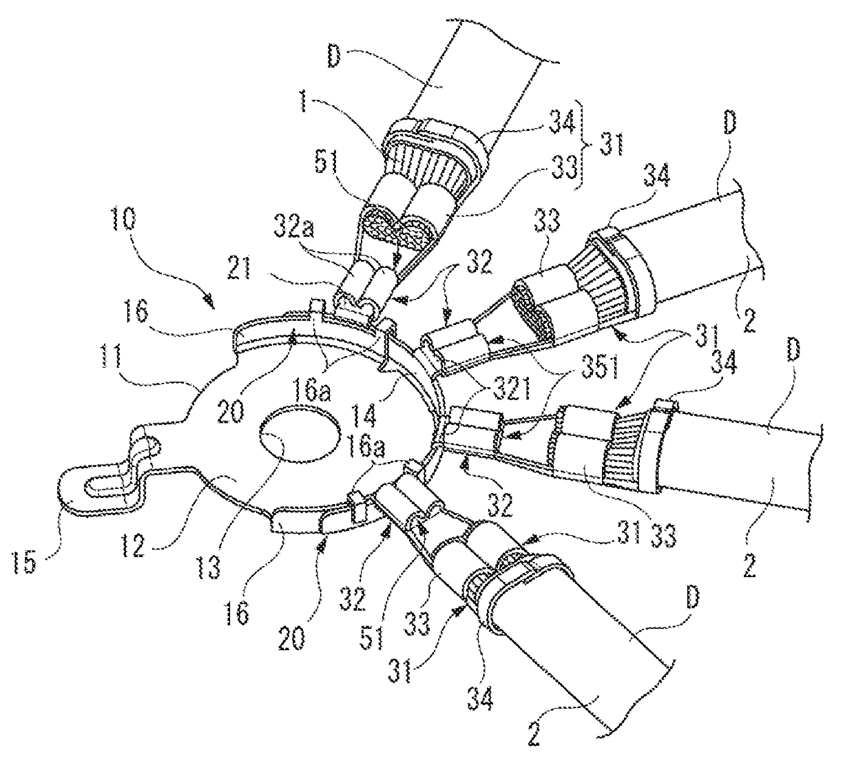
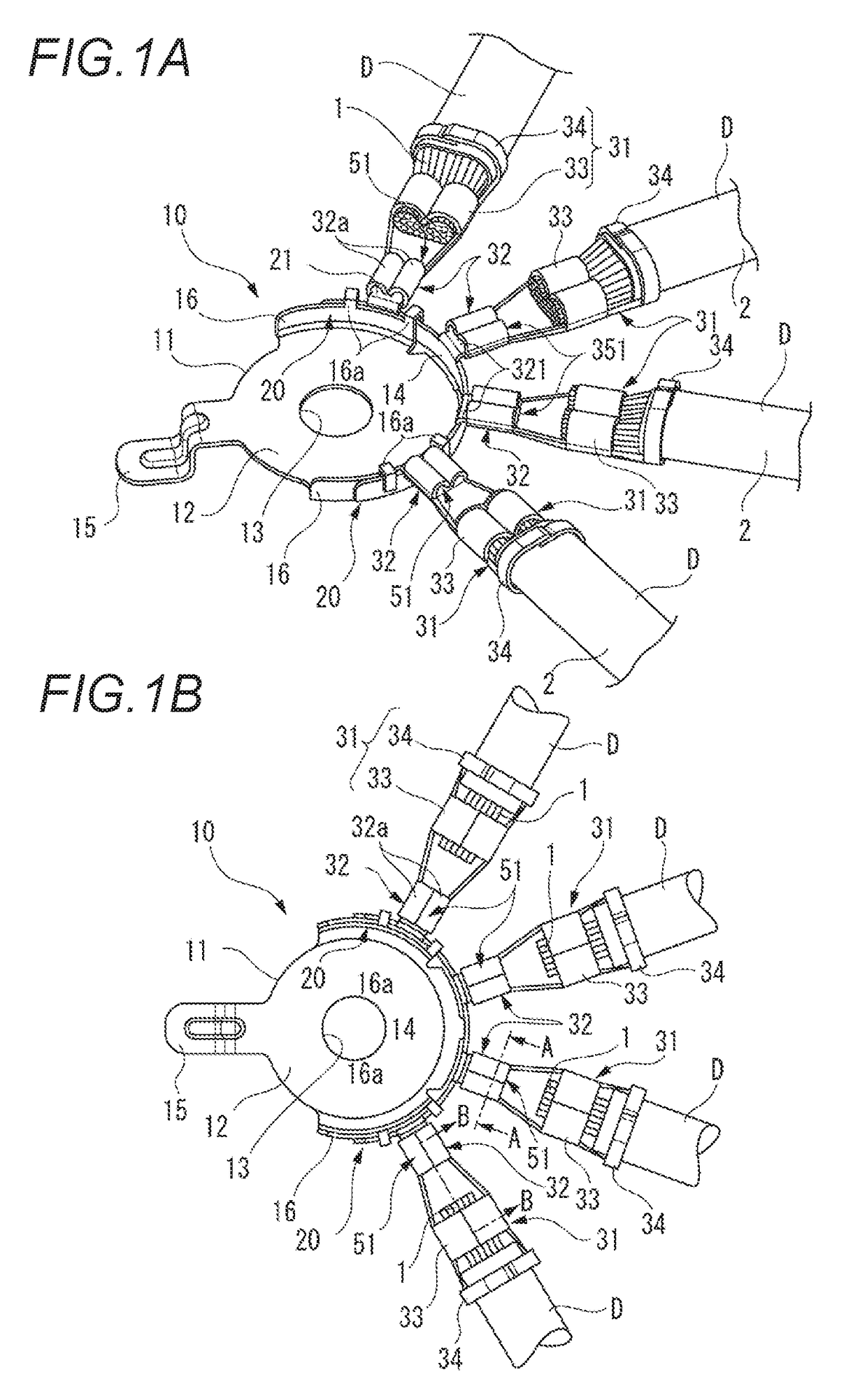
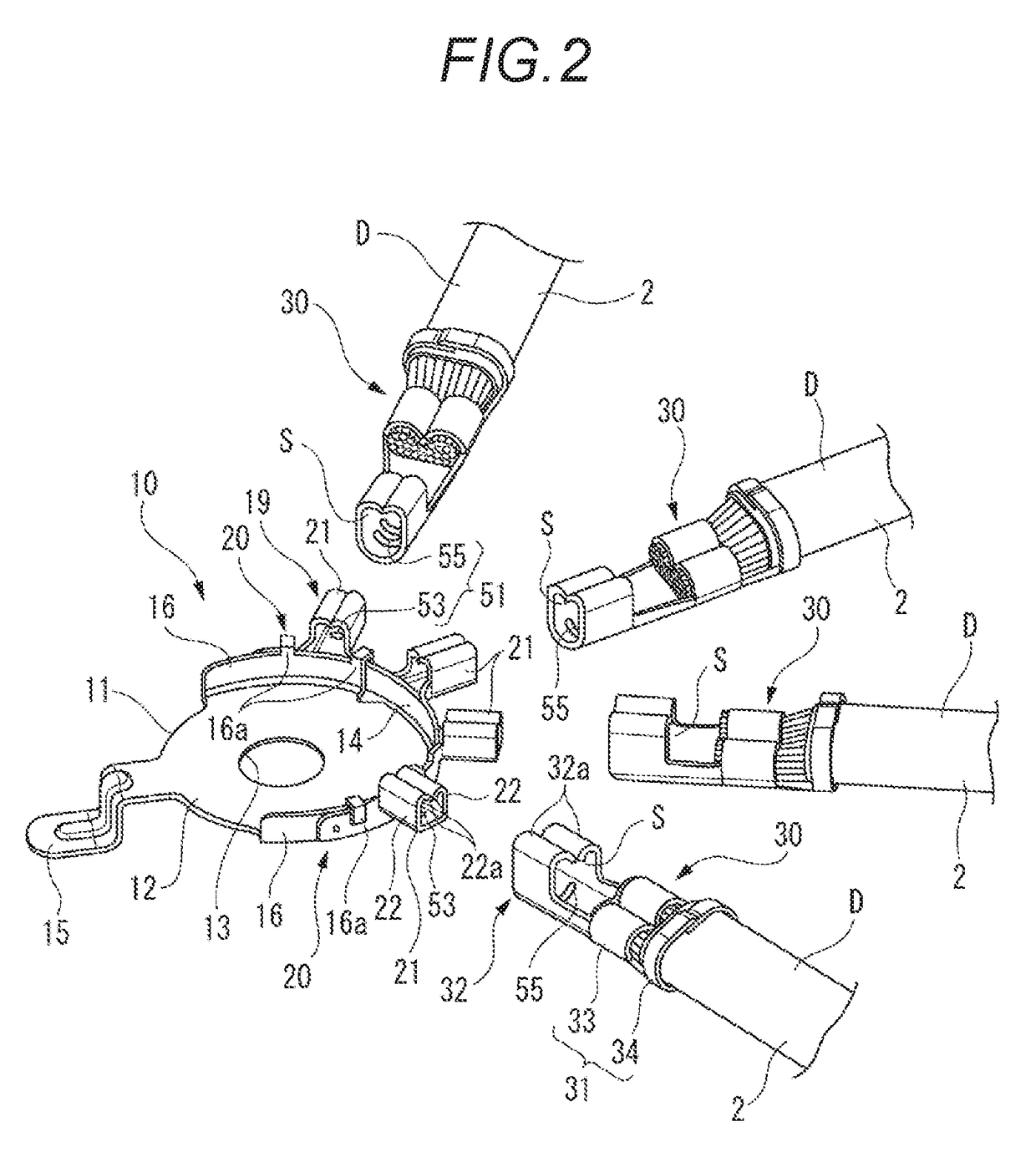
[0102]FIGS. 9A and 9B are views for explaining the connection structure of the terminal fitting according to the second embodiment. FIG. 9A is a perspective view of a terminal fitting 10 to which grounding electric wires D have been connected, and FIG. 9B is a plan view of the terminal fitting 10 to which the grounding electric wires D have been connected. FIG. 10 is a schematic perspective view of a crimping machine for explaining a connection method for the terminal fitting 10 according to the second embodiment.

[0103]As shown in FIGS. 9A and 9B, the terminal fitting 10 is connected to connection terminals 13...


PUM


Abstract

A connection structure of a terminal fitting includes the terminal fitting including a terminal body, and a plurality of terminal connection portions extending from the terminal body and connection terminals connected to end portions of electric wires. Each of the connection terminals includes a pair of fastening caulking pieces which erects on opposite side portions of a terminal bottom portion. The pair of the fastening caulking pieces are caulked with opposite side portions of a corresponding one of the terminal connection portions from outside so that the connection terminal is caulked and fastened to the terminal fitting. Concave-convex engagement portions are provided in opposed surfaces in which the terminal connection portion and the terminal bottom portion abut against each other. The terminal fitting is connected to the electric wires through the connection terminals.

Description

CROSS REFERENCE TO RELATED APPLICATIONS[0001]This application claims priority from Japanese Patent Application No. 2015-233574 filed on Nov. 30, 2015, the entire contents of which are incorporated herein by reference.BACKGROUND OF THE INVENTION[0002]Field of the Invention[0003]The present invention relates to a connection structure and a connection method for a terminal fitting.[0004]Description of Related Art[0005]There has been known a connection structure in which connection plates of a plurality of terminal fittings, to which grounding electric wires have been connected, are put on top of one another, a common bolt is inserted into mounting holes provided in the connection plates to thereby bolt and fasten the connection plates to a grounding surface (such as a predetermined place of a vehicle body), so that the grounding electric wires can be conductively connected to the grounding surface in a lump through the terminal fittings put on top of one another (for example, see Paten...

Claims


Application Information

Patent Timeline
Patent Type & Authority Applications(United States)
IPC IPC(8): H01R11/09H01R4/18H01R4/04H01R11/28
CPCH01R11/09H01R4/04H01R4/188H01R11/28H01R11/12H01R4/185H01R4/20
Inventor YAMAMOTO, TAKATATSUMITA, KEIICHI
Owner YAZAKI CORP
Why Eureka
Try Eureka