Variable barrier pitch correction

a variable barrier and pitch correction technology, applied in the field of multi-view directional display, can solve the problems of parallax barrier or lens system, viewer observes a stereoscopic image only in strict viewing zones, and increases the total system cost, and achieves good image quality

Inactive Publication Date: 2017-06-01
SHARP KK
View PDF4 Cites 18 Cited by
  • Summary
  • Abstract
  • Description
  • Claims
  • Application Information

AI Technical Summary

Benefits of technology

[0029]A seventh aspect of the invention provides a multiple view directional display comprising: an image display panel; a parallax optic; an observer tracking unit; and a control unit, the control unit adapted to assign data values to pixels of the image display panel such as to provide an interlacing pattern of a first image and a second image having a repeat length that is a non-integer number of pixels. Use of a non-integer NP interlace value makes it possible to provide good image quality even if the observer(s) move away from, or closer to, the display.

Problems solved by technology

A fixed parallax barrier or lens system has the disadvantage that the viewer observes a stereoscopic image only in strict viewing zones.
Adding a mechanical element to the system is likely to increase the total system cost, whilst the dependence on moving parts could decrease the system robustness.
Another concern is that the tracking speed of a mechanical system may not be fast enough to cope with rapid changes in user position.
This approach is not without drawbacks: making a high quality switchable LC barrier is technically very challenging.
The shutter must be controllable on a scale smaller than the display's pixels, which is technically complex.
Discrete switching of an electronic barrier causes problems with the brightness uniformity of the resulting image.
This system greatly increases head freedom, but introduces a very visible artefact when users switch between viewing windows.
Even with these developments, current head tracking 3D technologies are far from perfect.
In particular, adjusting for movements of the user towards or away from the display remains a major unsolved problem.

Method used


Image

  • Variable barrier pitch correction
  • Variable barrier pitch correction
  • Variable barrier pitch correction

Examples


embodiments

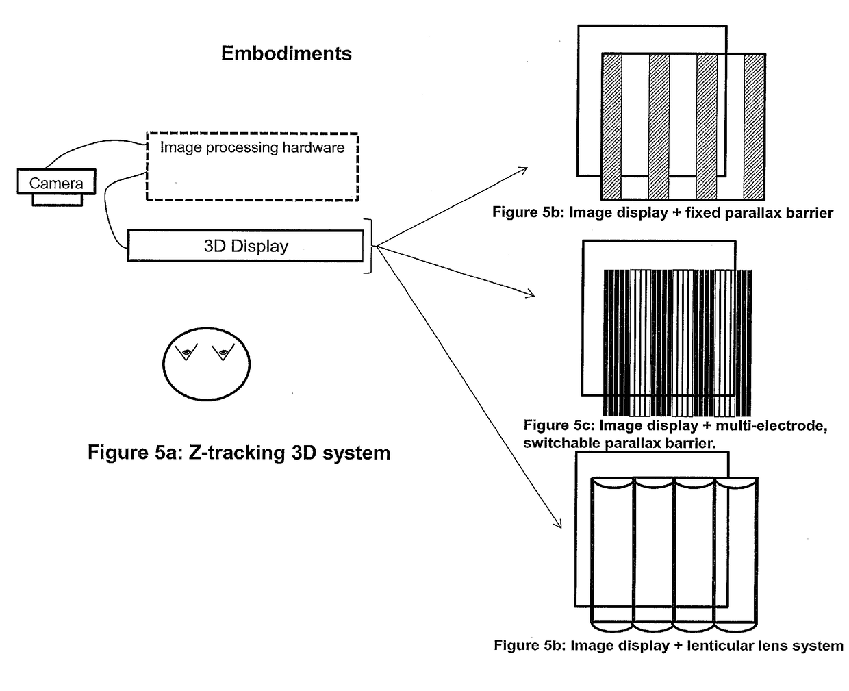
[0079]1. In a first embodiment, the tracking system is used in conjunction with a camera and fixed parallax barrier 3D display. Such a system is shown in FIG. 5a. A parallax system with a 6 sub-pixel repeating interlace pattern, a slanted barrier with a slope of 1 pixel per row and a slit width of 3 pixels (NP6-3 stag 1) gives very good tracking performance. This good performance is partly due to the ‘redundant’ sub-pixels that are initially hidden from the user and may be pre-loaded with view information. Correct view information can be maintained for each eye as the user moves and these hidden sub-pixels are revealed. The image processing hardware is configured to implement method one and / or method two as described above.

[0080]2. In a second embodiment, the tracking system is used in with a camera and a switchable parallax barrier. The barrier may be switchable in a discrete manner, as illustrated by FIG. 5c, with electrodes used to control spatial transmissivity. The barrier feat...


PUM


Abstract

Two methods are described for calculating the non-periodic display pixel pattern necessary for good viewing properties of a multiple view directional display with a fixed parallax barrier pitch. These methods could also be used to calculate optimum barrier pitch parameters for a display with a re-configurable parallax optic, such as a re-configurable parallax barrier, and a fixed pixel assignment, or to calculate hybrid system parameters in a display where the parallax optic (eg a parallax barrier) and the pixel assignment are both re-configurable. The first method uses a geometrical analysis to calculate a non-integer subpixel repeat unit for interlacing. In this approach interlacing starts at a point determined by the user's head position relative to the display. The non-integer number ensures that the interlace pattern inserts extra pixels where necessary in order to compensate for the user's head position. The second method uses a pixel-by-pixel calculation step, whereby every pixel's position relative to the user's eyes and the nearest slit of the barrier determines whether the pixel should show left-view or right-view information. This approach may be done for blocks of pixels, but performance is optimal when calculated on a pixel-by-pixel basis.

Description

TECHNICAL FIELD[0001]This invention relates to a multiple view directional display such as an autostereoscopic (glasses-free) 3D system that can maintain a 3D effect as a user moves closer to or further from the display. The invention is compatible with parallax barrier and lenticular lens systems. The invention could be used in other applications, for example to display different 2D content to multiple different users in the manner of commercial ‘Dual View’ displays.BACKGROUND ART[0002]For many years people have been trying to create better autostereoscopic 3D displays, and this invention provides a further advance in this field. An autostereoscopic display is a display that gives stereoscopic depth without the user needing to wear glasses. This is accomplished by projecting a different image to each eye. An autostereoscopic 3D display can be realised by using parallax optic technology such as a parallax barrier or lenticular lenses.[0003]The design and operation of parallax barrie...

Claims


Application Information

Patent Timeline
Patent Type & Authority Applications(United States)
IPC IPC(8): H04N13/04G02B30/28G02B30/31
CPCH04N13/0409H04N13/0497H04N13/0477H04N13/305H04N13/373H04N13/376H04N13/31H04N13/398G02B30/31G02B30/28G02B30/26G02B30/27
Inventor MATHER, JONATHANHUANG, LAURAZAWADZKI, ALEXANDERBRENNEN, FORREST
Owner SHARP KK
Why Eureka
Try Eureka