Design method of a rig

a design method and rig technology, applied in the field of orthopedic surgery, can solve the problem that the area of joint damage may not be easily covered by a single piece of equipmen

Active Publication Date: 2017-06-08
EPISURF IP MANAGEMENT
View PDF8 Cites 11 Cited by
  • Summary
  • Abstract
  • Description
  • Claims
  • Application Information

AI Technical Summary

Benefits of technology

[0015]The area of the joint damage may not be easily covered by a single circular implant if the damaged area is elongate or is irregular or large in shape. Instead of using a number of separate implants or an implant requiring complicated bone removal techniques, using several different drills and tools, the design method of the surgical implant and the rig according to embodiments herein provides a solution which also utilizes a single rig anchored in place for the entire pre-drilling and drilling operation.
[0016]In one embodiment the same double-drill, the same pre drilling guide socket and the same depth adjustment socket is used for all drillings. This is made possible by a rig which permits shifting of the guide socket or adjustment socket from one side to the other side or the other sides of the hollow shell interior between drillings. In one embodiment a movable interior arcuate wall insert can also be inserted in each position to provide a complete circular cylinder for holding the pre-drilling guide socket for each drilling. The socket may also be adjustable. In another embodiment the movable insert is not arcuate but is a cylinder. In another embodiment no insert at all is used. Other similar embodiments are of course also possible.
[0017]According to one embodiment, this will create two identical peg holes and an exactly excavated cavity to fit an implant in the form of two intersecting circles of the same diameter. Merely removing the insert wall in the cylindrical interior then creates a shell, a

Problems solved by technology

The area of the joint damage may not be easily covered by a single circular

Method used


Image

  • Design method of a rig
  • Design method of a rig
  • Design method of a rig

Examples


Embodiment Construction

Introduction

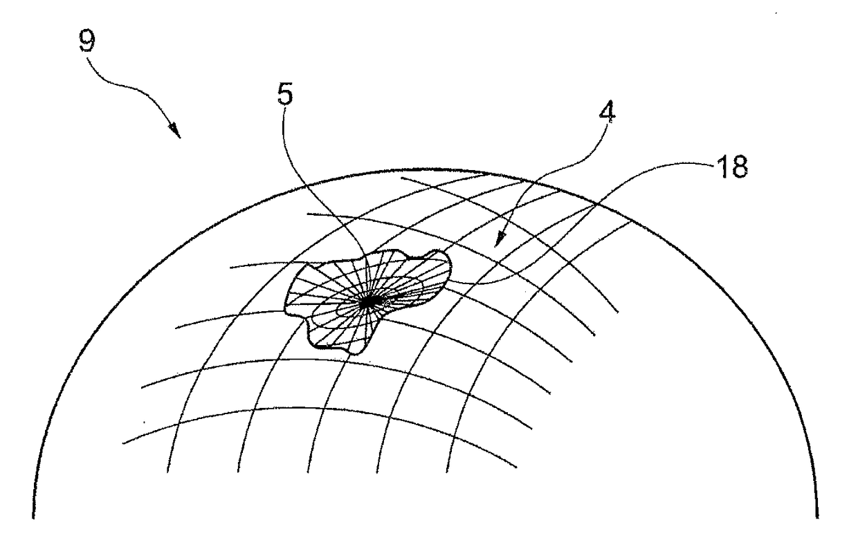
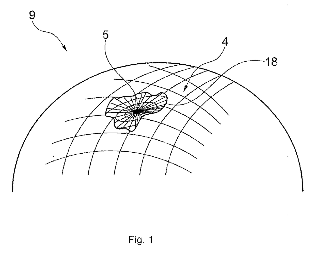
[0139]Embodiments herein relates to a design method for design of an individually customized rig 600 The rig 600 designed by the method according to embodiments herein is to be used for cartilage repair in a joint of a human or animal. The design method for design of an individually customized rig according to embodiments herein is described below.

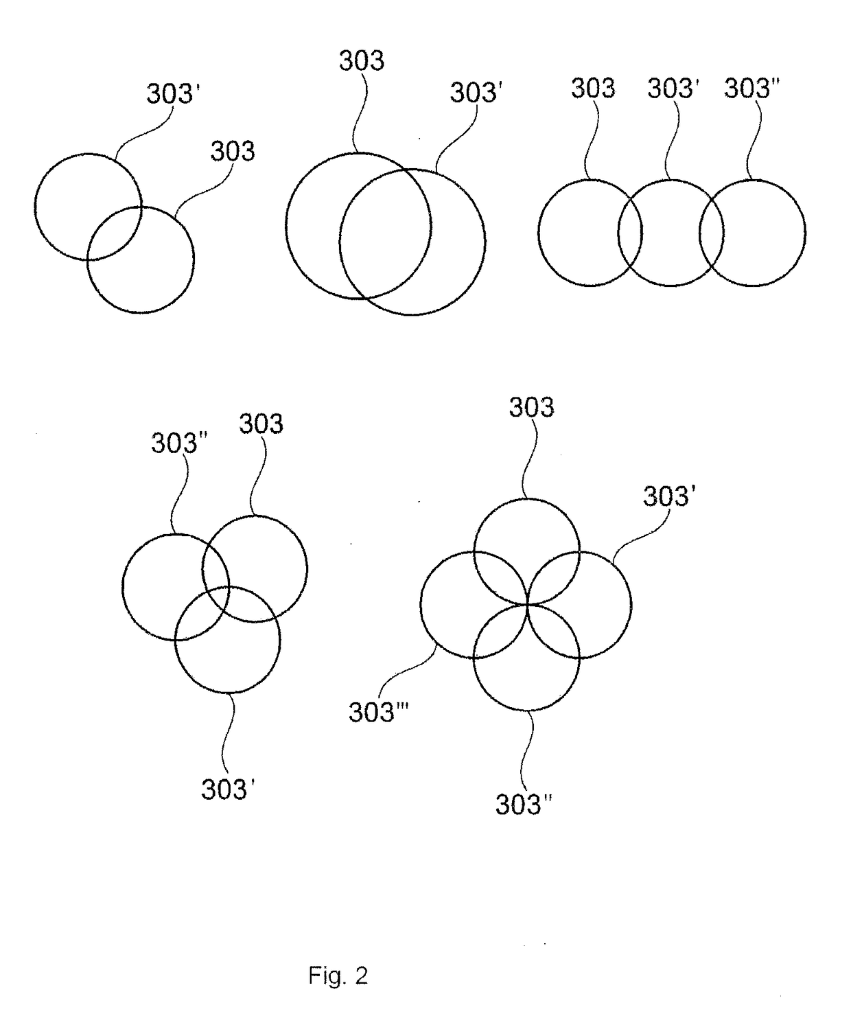
[0140]The rig comprises a hollow tubular shell, and the interior of the shell defines at least first and second intersecting cylinders. The design method comprises identifying a damage area, presenting a 3D view of the identified damage area and generating a 3D model of a virtual rig. The generating comprises virtually placing in 3D view a shape covering or partly covering damage area, and creating, based on the position of the virtually placed shape, a position of hollow tubular rig shell of the virtual rig. The method further comprises selecting the at least first and second intersecting cylinders of the virtual rig, based on...


PUM


Abstract

A design method for design of a rig is presented. The rig comprises a hollow tubular shell, and the interior of said shell defines at least first and second intersecting cylinders. The design method comprises identifying a damage area, presenting a 3D view of identified damage area and generating a 3D model of a virtual rig. The generating comprises virtually placing in 3D view a shape covering or partly covering damage area, and creating, based on the position of the virtually placed shape, a position of hollow tubular rig shell of the virtual rig. The method further comprises selecting the at least first and second intersecting cylinders of the virtual rig, based on the size and form of the virtually placed shape, and creating a positioning surface of the virtual rig which is a bone and/or cartilage-engaging end of hollow tubular shell. The positioning surface is adapted to follow the surface surrounding the virtually placed shape when the virtual rig is placed in a virtual model of the joint. The method comprises producing a rig according to the virtually created rig.

Description

TECHNICAL FIELD[0001]Embodiments herein relates in general to the field of orthopedic surgery and to cartilage and / or bone resurfacing. Embodiments herein relates to a rig intended for guiding replacement of a part of a bone and / or cartilage portion and to a design method of such a rig. Further embodiments herein also relates to a design method of an implant, surgery kits, kits of tools and a method for replacing a portion of an articular surface of a joint.BACKGROUND[0002]In the surgical operation of implanting small implants it is critical that the implant is positioned in a precise manner. If the implant is offset from its intended position it may cause increased wear or load on the joint. For example, if the implant is tilted this may result in an edge that projects above the cartilage surface and causes wear on the opposing cartilage in the joint. Another example is when the implant is placed in a position with the surface of the implant projecting above the surface of the cart...

Claims


Application Information

Patent Timeline
IPC IPC(8): A61F2/46A61B17/17A61F2/30A61B17/15A61F2/38A61F2/36
CPCA61F2/4657A61F2/38A61B17/17A61F2/30A61B17/15A61F2/36A61F2/30756A61B17/154A61B17/1767A61F2002/3013A61F2002/30331A61F2002/30878A61F2002/30891A61F2002/30892A61F2002/30897A61B34/10A61B2034/108
Inventor BAKE, NINALILLIESTR LE, RICHARD
Owner EPISURF IP MANAGEMENT
Why Eureka
Try Eureka