Self-Adhesive Balancing Weight for a Vehicle Wheel

Active Publication Date: 2017-06-08
WEGMANN AUTOMOTIVE GMBH & CO KG
View PDF9 Cites 1 Cited by
  • Summary
  • Abstract
  • Description
  • Claims
  • Application Information

AI Technical Summary

Benefits of technology

The patent describes a balancing weight for wheels that can be easily attached to the rim of a wheel. The balancing weight has curved sections that make contact with the rim at multiple points, resulting in a strong attachment. The distance between the balancing weight and the rim is slightly decreasing, which can be absorbed by a self-adhesive tape. The balancing weight can also be attached to a connecting means that can be a rod or belt, which allows for a flexible connection. The balancing weight can be attached to the rim by tilting it or moving it towards the rim, and then pressing it against the rim to ensure a secure attachment. This attachment method does not require the use of adhesive tape.

Problems solved by technology

Particularly, the counter-surface of aluminum wheel rims, to which the balancing weights have to be fixed, often are concave-convex shaped so that accurate adaptation of balancing weights is difficult.

Method used


Image

  • Self-Adhesive Balancing Weight for a Vehicle Wheel
  • Self-Adhesive Balancing Weight for a Vehicle Wheel
  • Self-Adhesive Balancing Weight for a Vehicle Wheel

Examples


first embodiment

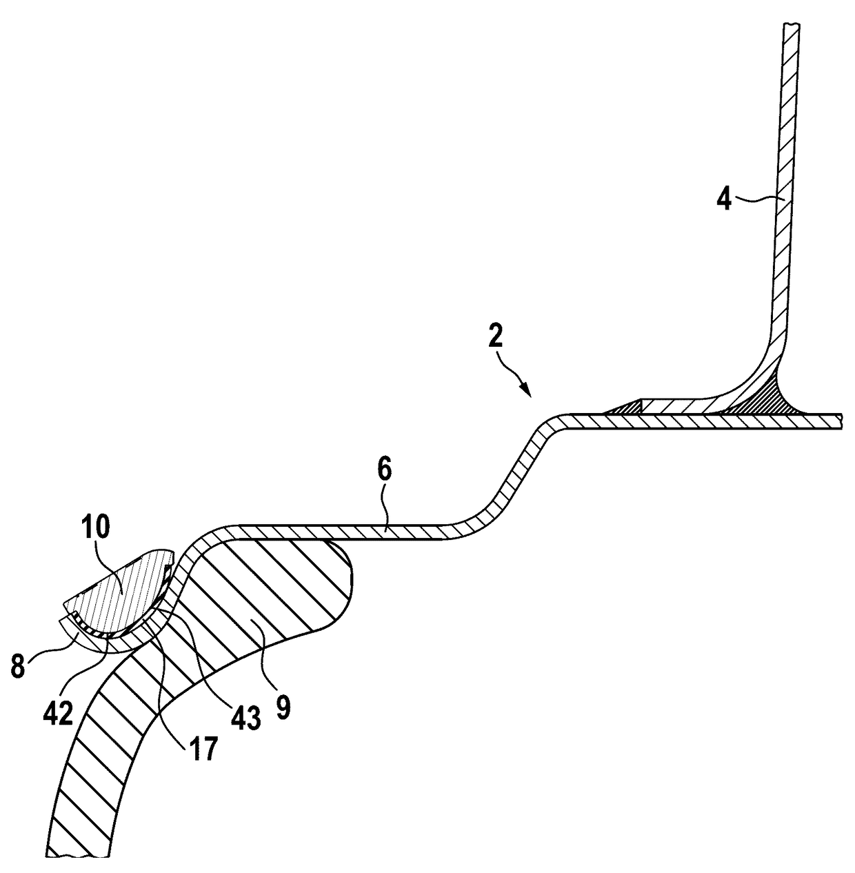
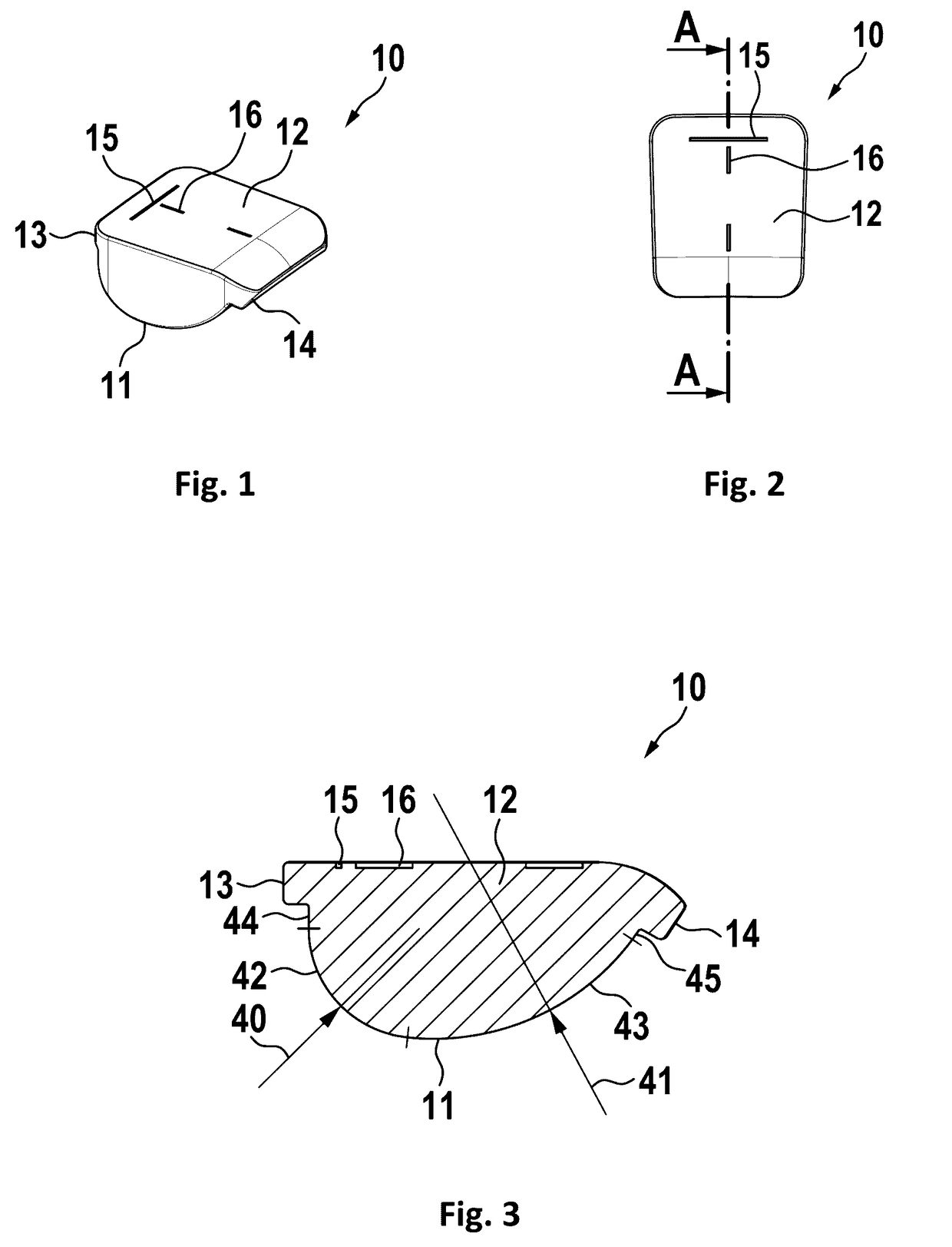
[0064]In FIG. 1, a first embodiment, preferably for steel rims is shown. A balancing weight 10 has a top surface 12 and a bottom surface 11 opposing to the top surface. The top surface may bear at least one marking and / or an ornamental design. In this embodiment, there is a first line 15 which shows the orientation of the balancing weight and is approximately parallel to the circumference of the rim; a second line 16, which may be under a right angle and comprises of two dashes in this embodiment, is in a radial direction and points towards the axis of the wheel. The bottom surface 11 has a specific contour to be adapted to a large number of different rims, which will be explained later in detail. For holding the balancing weight for an easy assembly to the rim, the balancing weight may have a first extension 13 and / or a second extension 14.

[0065]In FIG. 2, the first embodiment is shown in a top view. Here a sectional cut A-A is indicated, which will be shown in detail in the next f...

second embodiment

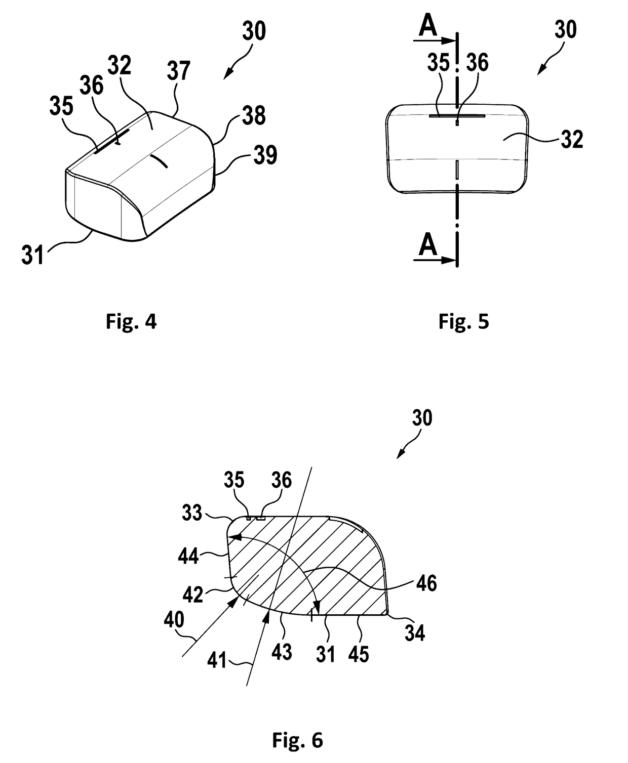
[0067]In FIG. 4, a second embodiment is shown which is preferably suited for aluminum rims. As known from the prior art, balancing weights previously could have been attached only to comparatively planar surfaces of aluminum rims. A balancing weight 30 according to this embodiment now may be attached to the outer edge of an aluminum rim, which significantly increases the flexibility and the possible range of application of balancing weights. Again, this balancing weight has a top surface 32 and a bottom surface 31. Again, there may be markings on the top surface, as described before. There may be a first line 35 approximately parallel to the circumference of the rim, and a second line 36 in radial direction, which may be directed toward the axis of the wheel. In this embodiment it is preferred, if the top surface is curved and preferably comprises of a first planar top surface section 37, a curved top surface section 38, and a second planar top surface section 39. It is preferred, i...

third embodiment

[0081]FIG. 18 shows a balancing weight 70 of a third embodiment, preferably for aluminum rims, with a connecting means in a sectional view. Here, the second radius is extremely large or it is even missing, so that there is no second curved section, resulting in a plane bottom surface. Preferably the balancing weight 30 has a cut-out or recess 48 for holding the connecting means 60.

[0082]FIG. 19 shows a connecting means 60. The connecting means 60 may have at least one projection 61 interfacing with a cavity 49 in a balancing weight to improve anchoring of the connecting means within the balancing weight.

[0083]FIG. 20 shows a chain of balancing weights from the bottom side. Here, preferably, gaps or cutouts 18 are provided in the self-adhesive tape, which allow easier bending to adapt to a radius of a rim.

[0084]FIG. 21 shows a preferred embodiment of a self-adhesive tape 17. Here, gaps or cutouts 18 are provided, which allow easier bending to adapt to a radius of a rim.

[0085]FIG. 22 ...


PUM


Abstract

A self-adhesive balancing weight for a vehicle wheel has a top surface and a bottom surface with a self-adhesive tape. The bottom surface has a first curved section with a first radius and a second curved section with a second radius. The first radius is smaller than the second radius. This allows to hold the balancing weight by the adhesive tape to almost every rim, as there are always at least two holding points (-lines) by which the balancing weight contacts the rim via the adhesive tape.

Description

PRIORITY CLAIM[0001]This application is a continuation of pending International Application No. PCT / EP2015 / 068901 filed on Aug. 18, 2015, which designates the United States and claims priority from European Application No. 14181854.2 filed on Aug. 21, 2014, each of which is incorporated herein by reference in its entirety.BACKGROUND OF THE INVENTION[0002]1. Field of the Invention[0003]The invention relates to a self-adhesive balancing weight, which may be attached to the rim of a wheel of a vehicle for balancing the wheel.[0004]2. Description of Relevant Art[0005]The contact surface of self-adhesive balancing weights generally is formed so as to accurately fit to the counter surface of the wheel rim holding the weight to provide as much contact surface and thereby adhesive surface area as possible in order to ensure safe fixation. As the rim profiles of different types of wheels—coming from different wheel manufactures for instance—differ in a wide range, a great number of different...

Claims


Application Information

Patent Timeline
IPC IPC(8): F16F15/32
CPCF16F15/324F16F15/328B60B15/28F16F15/32F16F15/34
Inventor HORNUNG, THOMAS
Owner WEGMANN AUTOMOTIVE GMBH & CO KG
Why Eureka
Try Eureka