Pressure limiting valve with a hydraulic seal ring

A technology for pressure limiting valves and sealing rings, which can be used in safety valves, balance valves, valve devices, etc., and can solve problems such as failure of pressure limiting valves

Inactive Publication Date: 2009-08-05
沃尔夫冈·福斯
View PDF6 Cites 0 Cited by
  • Summary
  • Abstract
  • Description
  • Claims
  • Application Information

AI Technical Summary

Problems solved by technology

The shape, construction and material of the known O-rings lead to the described unfavorable deformations and thus to premature failure of such safety-relevant pressure limiting valves.

Method used


Image

  • Pressure limiting valve with a hydraulic seal ring
  • Pressure limiting valve with a hydraulic seal ring
  • Pressure limiting valve with a hydraulic seal ring

Examples


Embodiment Construction

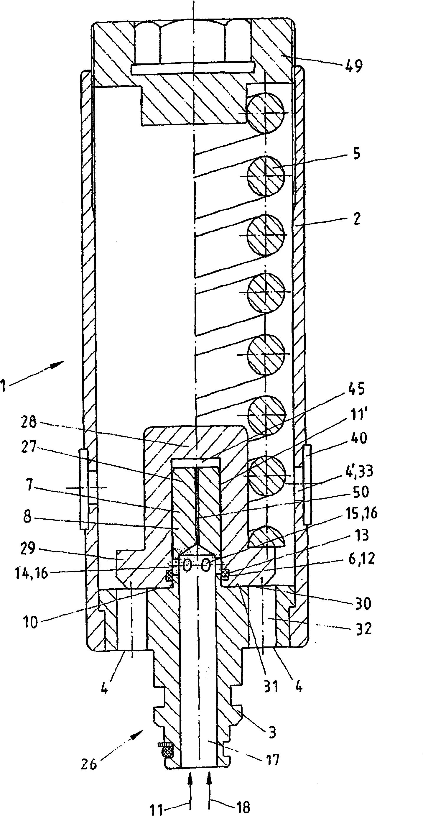
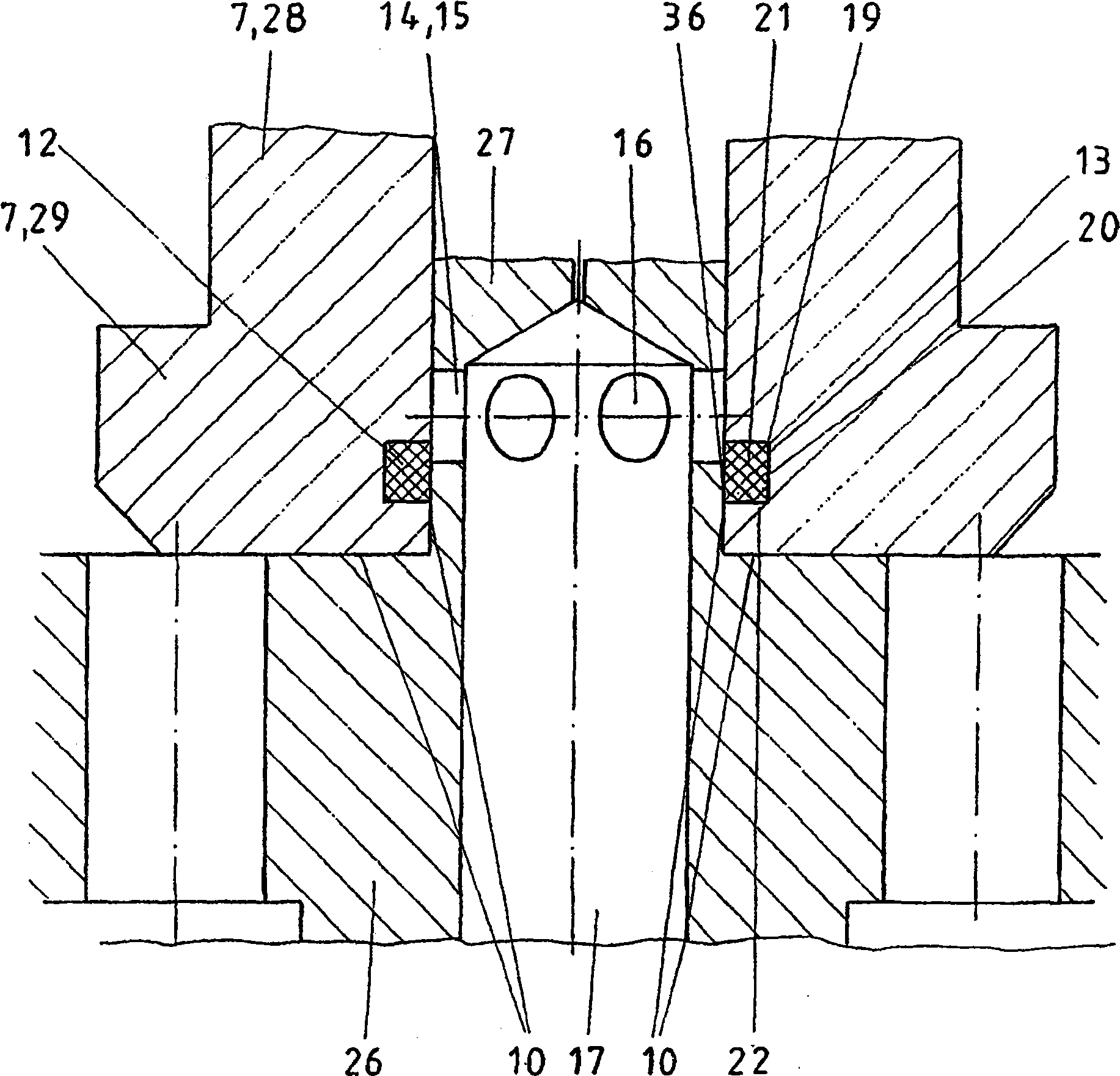
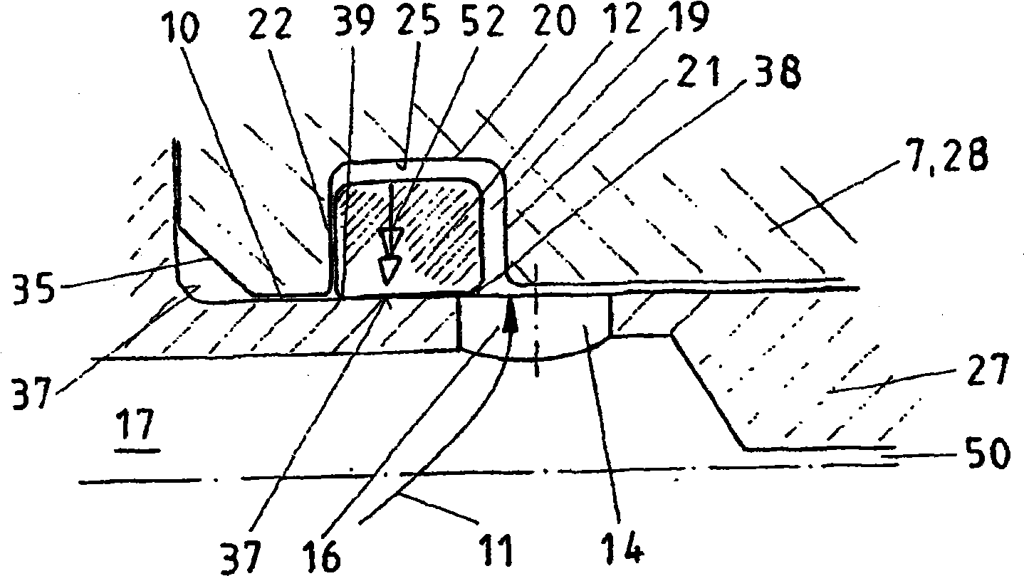
[0028] for in figure 1 In the pressure limiting valve 1 shown in , in addition to the special sealing device, the construction of the spring seat 7 and the connection 26 with the piston-shaped sleeve 27 is also of particular significance.

[0029] The pressure limiting valve 1 is shown in a sectional view, in which it can be clearly seen that the valve body 2 has a load connection 3 and a pressurized fluid outlet 4 , which are realized in the region of the connection 26 . Arranged in the valve body 2 is a valve spring 5 , which is supported on a spring retainer 7 , which is partly a moving closure 8 . The closing element 8 and the sealing element 6 are used to effectively separate the load connection 3 from the pressure fluid outlet 4 during the closed state of the pressure limiting valve 1 .

[0030] The connection between the load connection 3 and the pressurized fluid outlet 4 is indicated by a flow gap 10 . available from figure 1 It can be seen in the figure that her...


PUM


Abstract

The invention relates to a pressure limiting valve with a hydraulic seal ring (12), characterized in that the sealing element (6), for securing the flow gap (10) between the consumer connection (3) and the pressurized fluid outlet (4), is embodied as a seal ring (12) with a limited flexibility. Said seal ring (12) is inserted without preload into a groove (13) provided therefore, whereby said groove (13) is embodied so as to allow the flow of pressurized fluid (11) behind the seal ring (12).

Description

technical field [0001] The invention relates to a pressure limiting valve for preventing overloading of hydraulic installations, in particular in underground mining and tunneling against ground pressure impacts (Gebirgsschlag) of hydraulic struts (Hydraulikstempel), with a pressure limiting valve having a load connection and the valve body of the pressure fluid outlet, the load connection and the pressure fluid outlet are separated from each other by a closure with a seal that seals (sichernd) the flow gap between the pressure fluid outlet and the load connection, which moves against the force of the valve spring , and are interconnected for discharge of pressurized fluid in the event of overload. Background technique [0002] Pressure limiting valves are used in different hydraulic fields and are mainly used to protect hydraulic equipment from overloading. In this case, a valve piston is generally arranged in the valve body, so that in the event of an overload, the valve p...

Claims


Application Information

Patent Timeline
Patent Type & Authority Patents(China)
IPC IPC(8): F16K17/04
CPCF16K17/046Y10T137/7925Y10T137/7834F16K17/0433F16K17/0466
Inventor 沃尔夫冈·福斯
Owner 沃尔夫冈·福斯
Why Eureka
Try Eureka