
Electromagnetic valve

Active Publication Date: 2017-06-08
HONDA MOTOR CO LTD +1
View PDF0 Cites 1 Cited by
  • Summary
  • Abstract
  • Description
  • Claims
  • Application Information

AI Technical Summary

Benefits of technology

The electromagnetic valve described in this patent can become larger as the coil spring is added. The problem is that a permanent magnet used to push the plunger that opens and closes the valve needs to be larger to compensate for the added spring force. This makes the valve bigger and more expensive.

Problems solved by technology

In the electromagnetic valve described above, there is a problem in that the electromagnetic valve is easily enlarged as a coil spring is provided.
For this reason, there is a problem in that a permanent magnet applying a magnetic force to the plunger is easily enlarged and, as a result, a size of the electromagnetic valve is further easily increased.

Method used


Image

  • Electromagnetic valve
  • Electromagnetic valve
  • Electromagnetic valve

Examples


Embodiment Construction

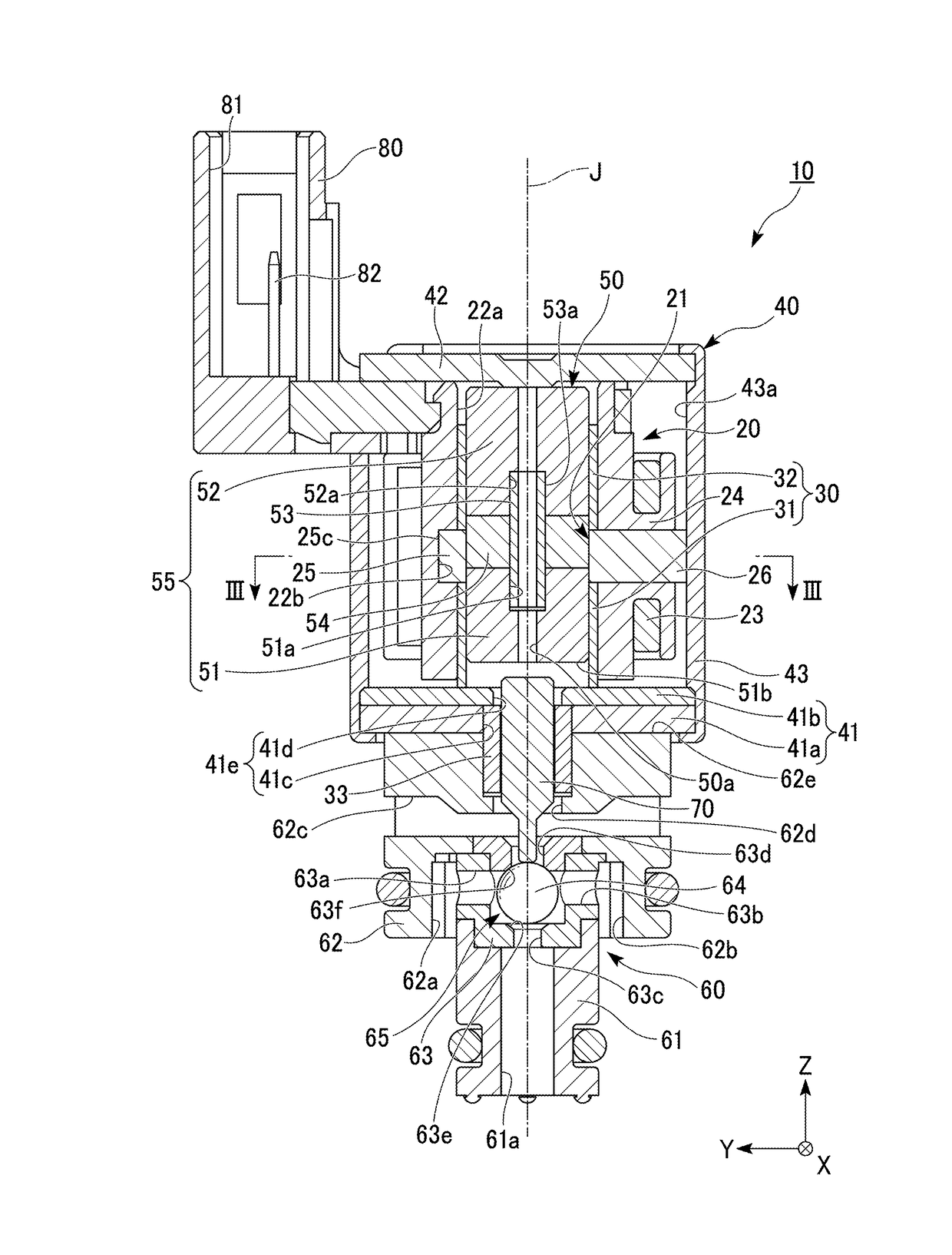
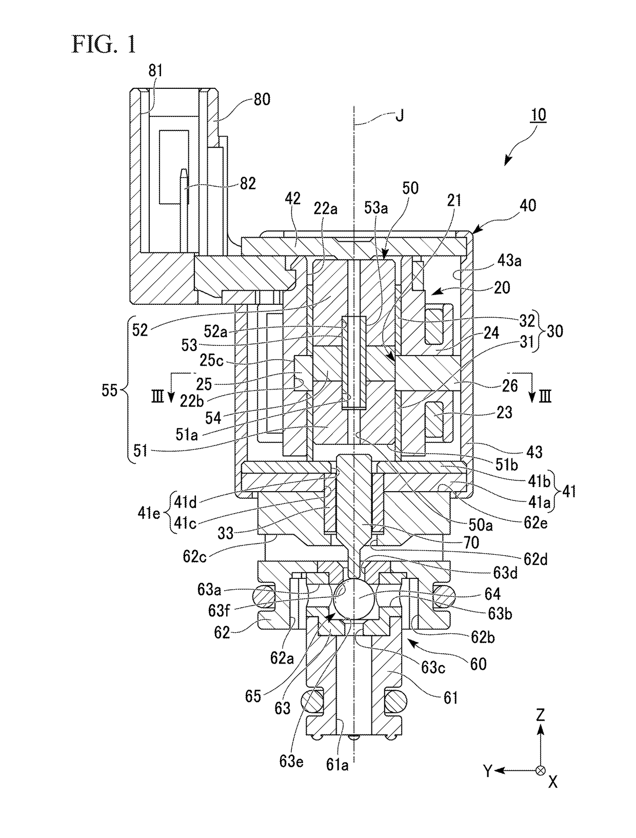
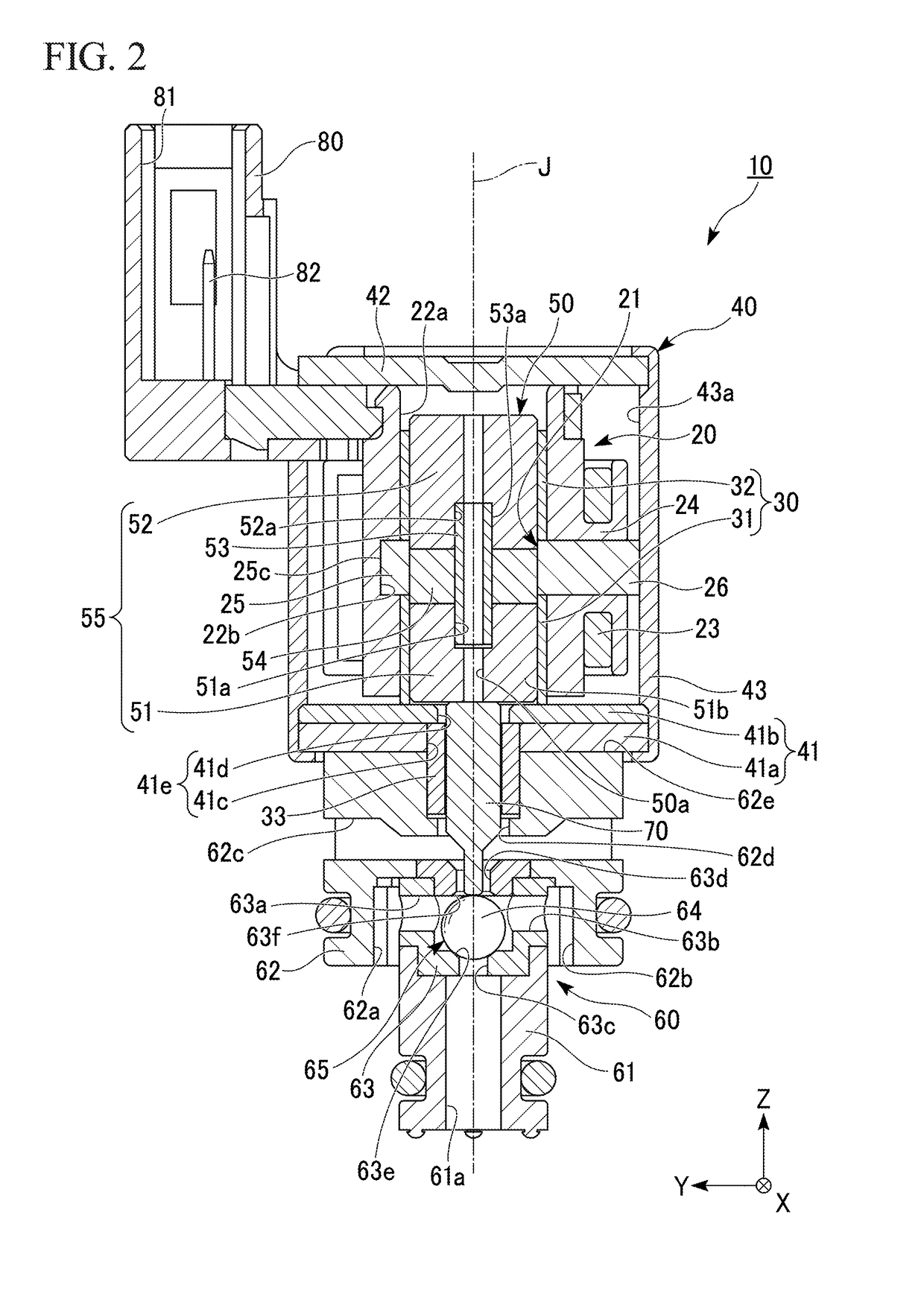
[0014]Hereinafter, an electromagnetic valve according to an embodiment of the present invention will be described with reference to the drawings. The scope of the present invention is not limited to the following embodiment, but the embodiment can be arbitrarily modified without departing from the technical spirit of the present invention. An actual structure and each structure may be different from each other in scale or number in the following drawings to facilitate understanding of each constitution.

[0015]In the drawings, an XYZ coordinate system is shown as a proper three-dimensional orthogonal coordinate system. In the XYZ coordinate system, a Z-axial direction is set as a direction parallel to an axial direction of a central axis J illustrated in FIG. 1. A Y-axial direction is set as one of directions perpendicular to the Z-axial direction, i.e. a leftward / rightward direction in FIG. 1. An X-axial direction is set as a direction orthogonal to both the Z-axial direction and the...


PUM


Abstract

An electromagnetic valve includes: a solenoid having a tubular guide part having the same center as a central axis extending in an axial direction; a movable element disposed inside the guide part and movable in the axial direction; a cover housing the solenoid and the movable element, defining a hole portion, and made of a magnetic material; a pin located at the hole portion and movable along with movement of the movable element; and a valve section provided outside the cover and opened / closed along with movement of the movable element and the pin. The solenoid has a core that surrounds an outer side of the movable element in the radial direction, and a coil that magnetizes the core. The core has an annular ring part surrounding the outer side of the movable element, and tooth parts protruding radially outward from the ring part on which the coil is mounted.

Description

CROSS-REFERENCE TO RELATED APPLICATION[0001]Priority is claimed on Japanese Patent Application No. 2015-236926, filed on Dec. 3, 2015, the contents of which are incorporated herein by reference.BACKGROUND OF THE INVENTION[0002]Field of the Invention[0003]The present invention relates to an electromagnetic valve.[0004]Description of Related Art[0005]A latch type electromagnetic valve equipped with a permanent magnet is disclosed, for instance, in Japanese Unexamined Patent Application, First Publication No. 2002-250457. The electromagnetic valve of Japanese Unexamined Patent Application, First Publication No. 2002-250457 is provided with a coil spring, and thereby maintains a valve-opened state or a valve-closed state in a state in which a current carried to a coil member is obstructed.SUMMARY OF THE INVENTION[0006]In the electromagnetic valve described above, there is a problem in that the electromagnetic valve is easily enlarged as a coil spring is provided. For example, upon movin...

Claims


Application Information

Patent Timeline
IPC IPC(8): F16K31/08H01F7/08H01F27/26H01F27/32F16K31/06H01F27/24
CPCF16K31/082F16K31/0665F16K31/0675H01F7/081H01F27/266H01F27/325H01F27/24
Inventor FUJITA, AKIRAUE, HIROAKIKAI, FUMIOYASUDA, TOMOHIRO
Owner HONDA MOTOR CO LTD
Learn More