Structure of air-packing device

a technology of air-packing device and structure, which is applied in the direction of packaging goods, transportation and packaging, damagable goods packaging, etc., can solve the problems of not being able to recycle styrofoam, soot is produced, flake or chip comes off, etc., and achieves the effect of improving reliability and easy enlargement of the opening

Inactive Publication Date: 2009-09-08
AIR PAQ
View PDF11 Cites 11 Cited by
  • Summary
  • Abstract
  • Description
  • Claims
  • Application Information

AI Technical Summary

Benefits of technology

[0009]It is, therefore, an object of the present invention to provide a structure of an air-packing device for packing a product that can minimize a shock or vibration and protect the product.
[0010]It is another object of the present invention to provide a structure of an air-packing device for packing a product by a packing space created by the air-packing device through a top opening which is designed to easily open and close the air-packing device.
[0015]According to the present invention, the air-packing device forms a flap portion that allows a user to easily enlarge the opening of the air-packing device for placement and removal of the package to be protected. The structure of the air-packing device under the present invention allows to securely hold the package in the air-packing device. Reliability is improved due to check valves that are provided to each air container.

Problems solved by technology

Although the styrofoam package material has a merit such as a good thermal insulation performance and a light weight, it has also various disadvantages: recycling the styrofoam is not possible, soot is produced when it burns, a flake or chip comes off when it is snagged because of it's brittleness, an expensive mold is needed for its production, and a relatively large warehouse is necessary to store it.
Third, the air-packing device does not produce a chip or dust which may have adverse effects on precision products.

Method used


Image

  • Structure of air-packing device
  • Structure of air-packing device
  • Structure of air-packing device

Examples


first embodiment

[0034]the air-packing device according to the present invention is described with reference to FIG. 3A-3B, 4A-4B, 5A-5B, 7 and 7A-7D. This embodiment of the air-packing device can be advantageously used to pack a product having a substantially flat box shape, such as a notebook computer, a DVD player, etc. The air-packing device of the present invention is designed to have a top opening which allows easily opening and closing operations for installing or removing the product to be protected through the top opening.

[0035]FIG. 3A is a perspective view of an air-packing device 101 which is inflated by the compressed air but a product to be protected is not placed therein. The air-packing device 101 has a top opening 131 through which a product or a package having the product is introduced to the inner space. FIG. 3A shows the situation where the air-packing device is slightly opened at the top from the steady state.

[0036]Typically, the air-packing device 101 is configured by a pluralit...

second embodiment

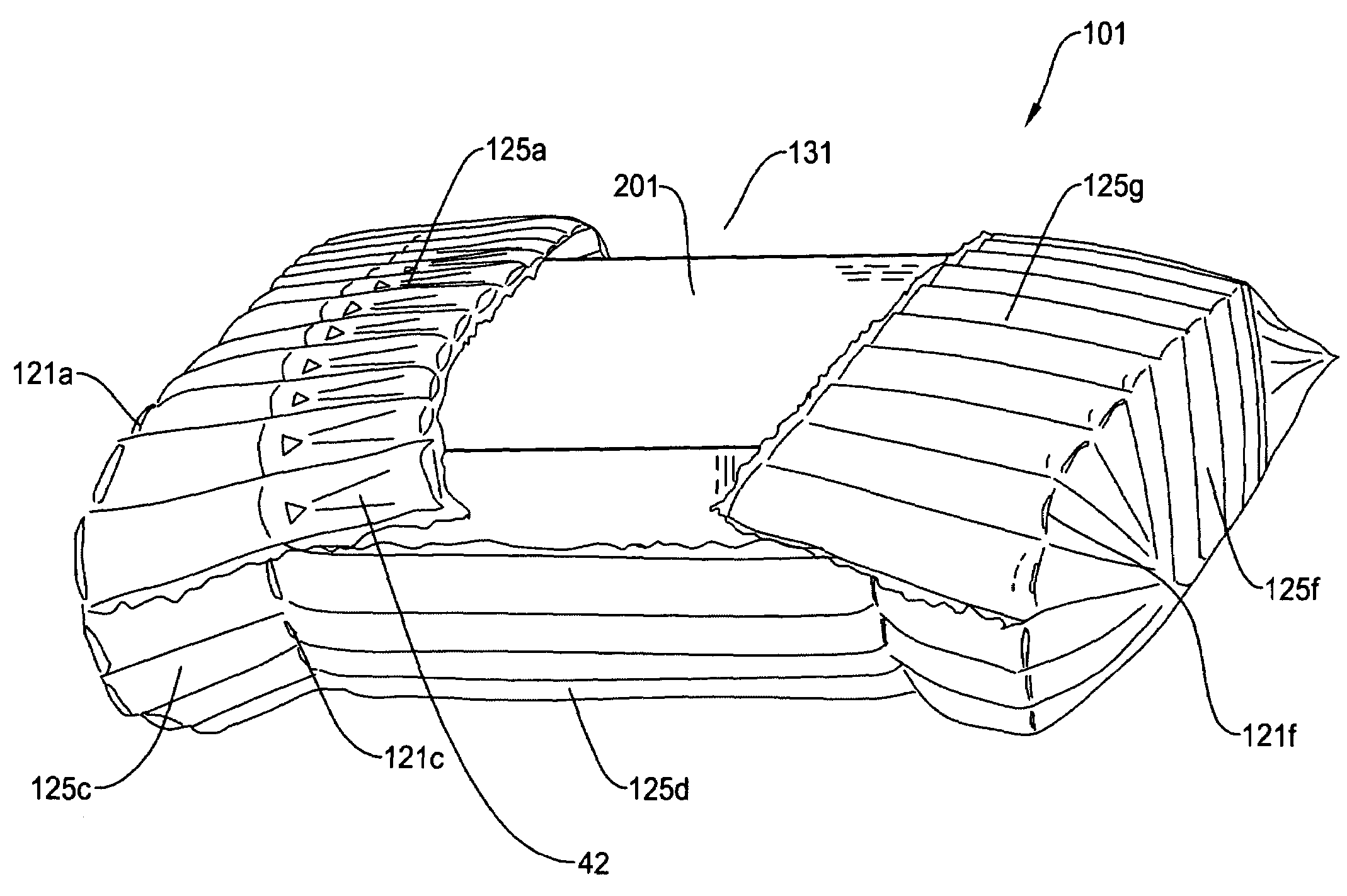
[0054]FIG. 8A is a perspective view showing the air-packing device of the present invention where the air-packing device 201 is closed. The air-packing device 201 is configured by a plurality of air-containers where each air-container has a plurality of air cells 225a-225f connected in series. In FIG. 8A, the air-packing device 201 is closed, in FIG. 8B, the air-packing device 201 is opened for installing or removing the product, and in FIG. 8C, a product such as a bottle is packed in the air-packing device 201. In this example, a flap portion for opening and closing the air-packing device 201 is mainly comprised of the air cells 225a.

[0055]Typically, the air-packing device 201 is configured by a plurality of air-containers where each air-container has a plurality of air cells 225a-225f connected in series. The air-packing device 201 is first produced in a sheet like form as shown in FIG. 10 and is folded and bonded through the process of FIGS. 11A-11D. Then, by supplying the compr...


PUM


Abstract

An air-packing device has an improved shock absorbing capability to protect a product in a container box. The air-packing device is comprised of first and second thermoplastic films where predetermined portions are bonded thereby creating a plurality of air containers, a plurality of heat-seal lands each sealing the first and second thermoplastic films in a small area of the air container thereby creating a plurality of series connected air cells for each air container, a plurality of check valves for corresponding air containers for allowing the compressed air to flow in a forward direction. A bendable flap portion is created that facilitates opening and closing operations so that a product to be protected can be easily placed or removed.

Description

FIELD OF THE INVENTION[0001]This invention relates to a structure of an air-packing device for use as packing material, and more particularly, to a structure of an air-packing device and check valves incorporated therein for achieving an improved shock absorbing capability to protect a product from a shock or impact by packing the product within a space having a shape unique to the product while allowing easy placement and takeout of the package.BACKGROUND OF THE INVENTION[0002]In product distribution channels such as product shipping, a Styrofoam packing material has been used for a long time for packing commodity and industrial products. Although the styrofoam package material has a merit such as a good thermal insulation performance and a light weight, it has also various disadvantages: recycling the styrofoam is not possible, soot is produced when it burns, a flake or chip comes off when it is snagged because of it's brittleness, an expensive mold is needed for its production, a...

Claims


Application Information

Patent Timeline
Patent Type & Authority Patents(United States)
IPC IPC(8): B65D81/02
CPCB65D81/052B65D65/44
Inventor YOSHIFUSA, KARK K.
Owner AIR PAQ
Why Eureka
Try Eureka