Support Stand for Heating Tools

a technology for supporting stands and heating tools, which is applied in the direction of manufacturing tools, soldering devices, lighting and heating apparatus, etc., can solve the problems of injuring the operator and easily damage the electrical components of devices, and achieve the effect of not damage electrical components

Inactive Publication Date: 2017-06-15
HAKKO CO LTD
View PDF5 Cites 4 Cited by
  • Summary
  • Abstract
  • Description
  • Claims
  • Application Information

AI Technical Summary

Benefits of technology

[0004]The present invention provides various alternative embodiments of a support stand for heating devices that may accommodate a number of different heating devices and user preferred positioning of the h...

Problems solved by technology

However, the heating devices may easily damage electrical components...

Method used


Image

  • Support Stand for Heating Tools
  • Support Stand for Heating Tools
  • Support Stand for Heating Tools

Examples


Embodiment Construction

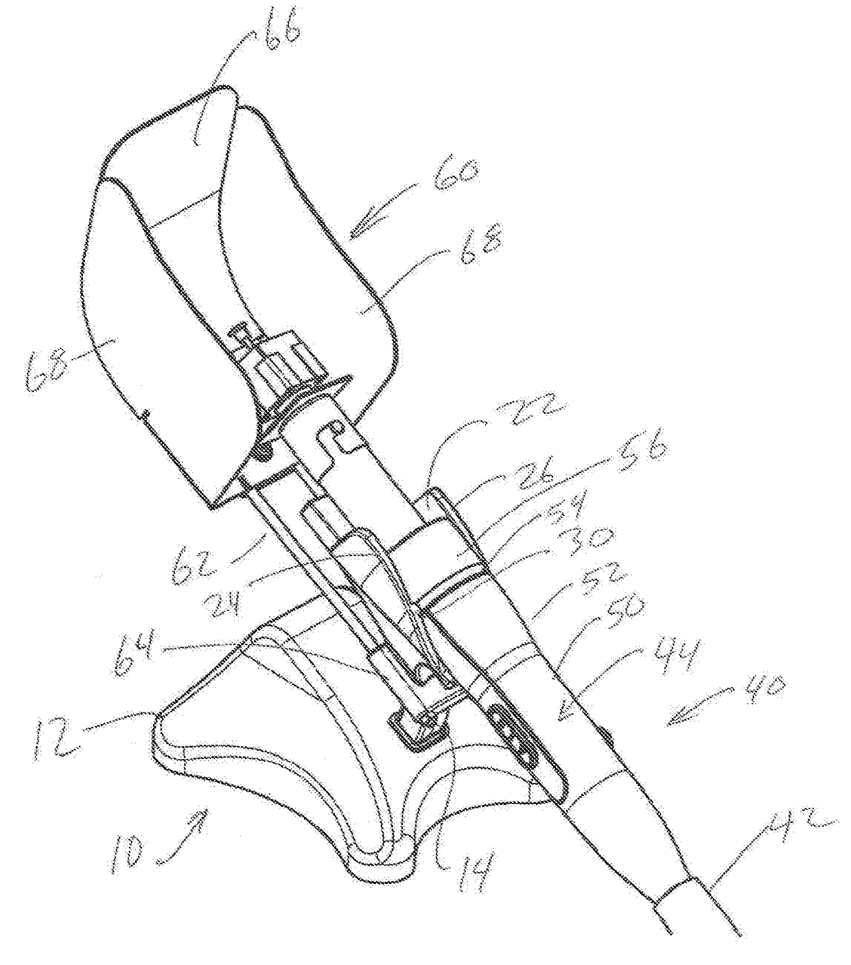
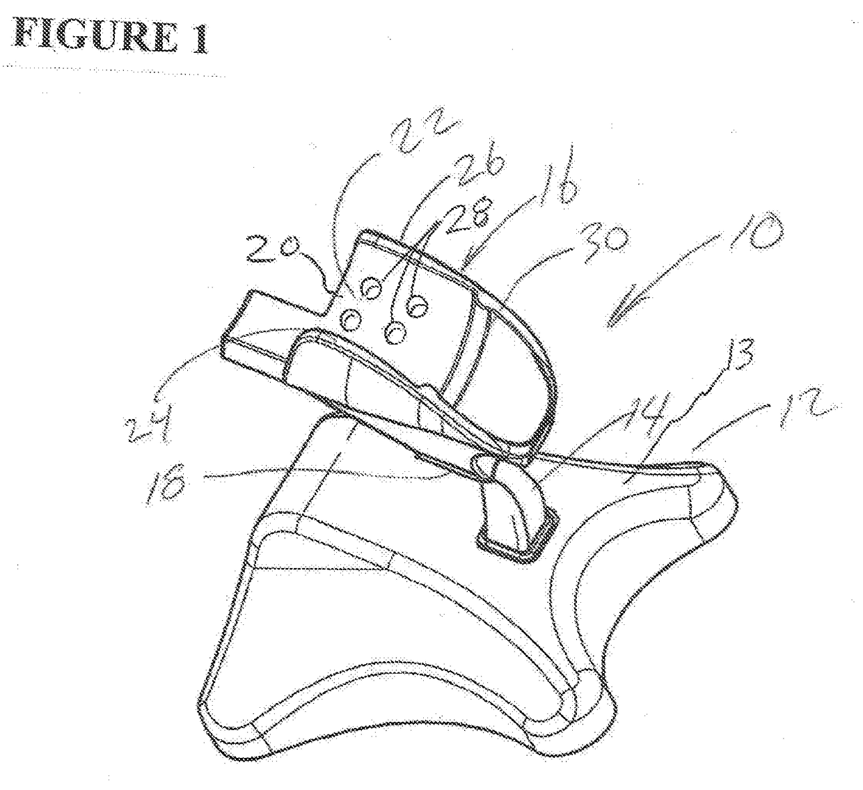
[0017]FIG. 1 is a perspective view of a first embodiment of a support stand 10. The support stand includes a base 12 including a sloped upper surface 13, a leg member 14 and a cradle 16. The cradle 16 includes a mount 18 to secure the leg member 14 to the cradle. Alternatively, the mount 18 may be configured so that the leg member 14 may be removable to allow easy repair or replacement. The cradle 16 defines a partial generally cylindrical section 20 defining an inner surface 22, a first upwardly projecting side 24 and a second upwardly projecting side 26 so that a handle of a heating device may be rested in a space between said first side and said second side as described below. The cradle 16 further includes at least one type of projection 30 on the inner surface 22, strategically positioned to allow balance.

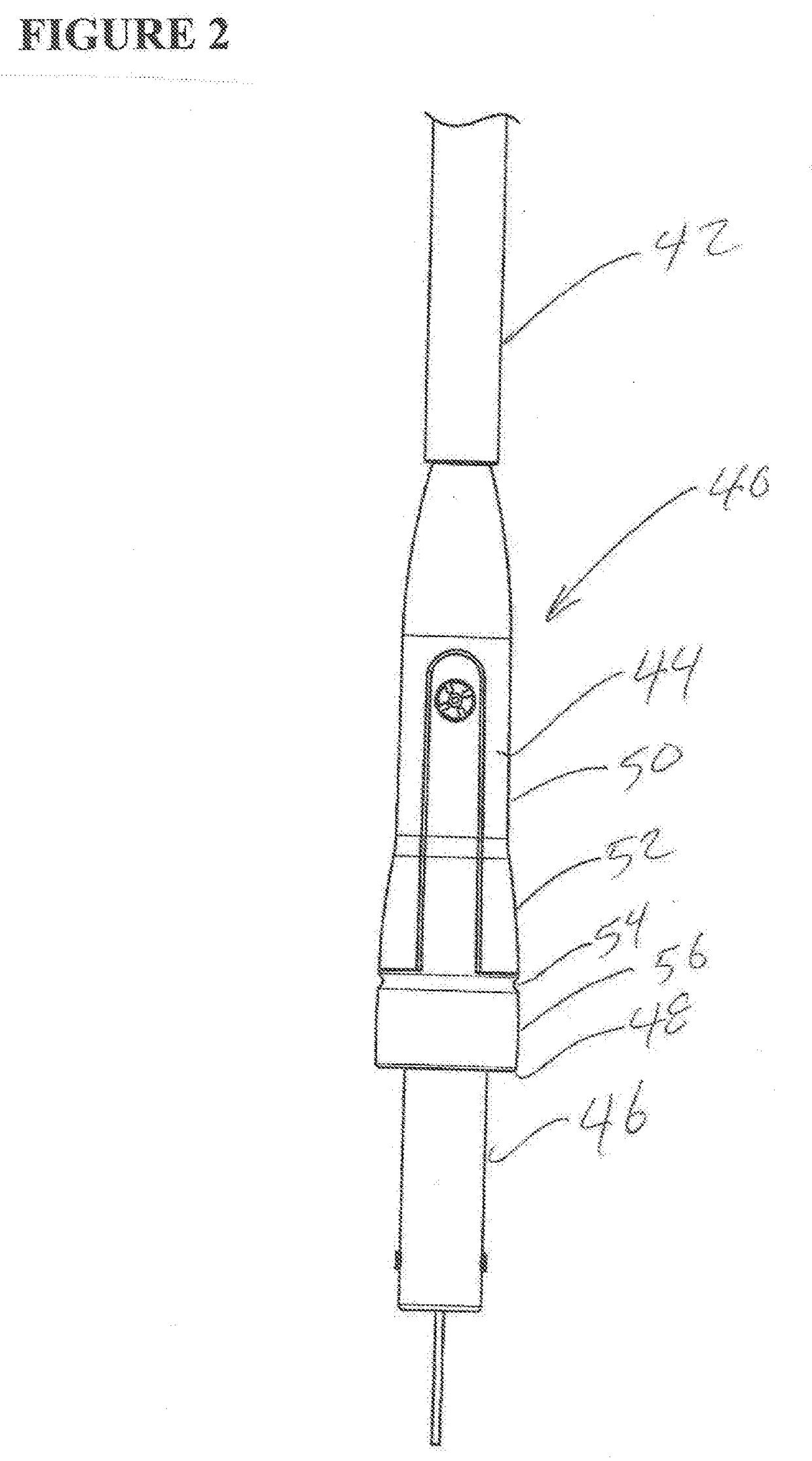
[0018]FIG. 2 is a perspective view of an exemplary configuration of a heating device 40. The heating device 40 may be a hot air blower, a soldering iron, a de-soldering tool o...


PUM

PropertyMeasurementUnit
Lengthaaaaaaaaaa
Angleaaaaaaaaaa
Diameteraaaaaaaaaa

Abstract

A support stand for a soldering or de-soldering handheld tool comprises a base and a cradle for supporting the handheld tool when it is not in use that protects the surrounding work area and accommodates user preferences.

Description

FIELD OF THE INVENTION[0001]The present invention relates to a support stand which supports a heating tool.BACKGROUND OF THE INVENTION[0002]The assembly and repair of electrical devices generally requires a human operator to utilize several different tools, including various hand-held heating devices such as a soldering iron for electrically securing components, a de-soldering tool for melting and removing solder to allow rework or repair, and a hot air device that may be required for heat shrink insulation. Often the operator may require all of these heating devices, along with a number of hand tools and electrical components, on the work surface of a work bench to work efficiently. However, the heating devices may easily damage electrical components, or injure the operator if they are carelessly set aside when not in use.[0003]A diligent user may prefer placing the heating devices in some type of holder or support stand. The positioning of the heating devices in the holder or stan...

Claims


Application Information

Patent Timeline
IPC IPC(8): B23K3/02F24H3/04
CPCB23K3/027B23K2201/36F24H3/0423B23K3/029B23K3/00B23K3/087B23K1/0016B23K2101/36
Inventor TERAOKA, YOSHITOMONEMOTO, HISAO
Owner HAKKO CO LTD
Why Eureka
Try Eureka