Bi-Directional Air-Curtain For Cold Testing A Camera

a camera and air-curtain technology, applied in the field of cold testing systems of cameras, can solve the problems of inability to fit in an economically priced test chamber, too large target sizes used to determine the operation and performance of a camera, and inability to test the image in a reasonable amoun

Active Publication Date: 2017-06-15
APTIV TECH LTD
View PDF11 Cites 9 Cited by
  • Summary
  • Abstract
  • Description
  • Claims
  • Application Information

AI Technical Summary

Problems solved by technology

However, the targets used to determine the operation and performance of a camera may be too large to fit inside an economically priced test-chamber.
However, the multi-pane configuration causes an unacceptable amount of image distortion for camera testing.

Method used


Image

  • Bi-Directional Air-Curtain For Cold Testing A Camera
  • Bi-Directional Air-Curtain For Cold Testing A Camera
  • Bi-Directional Air-Curtain For Cold Testing A Camera

Examples


Embodiment Construction

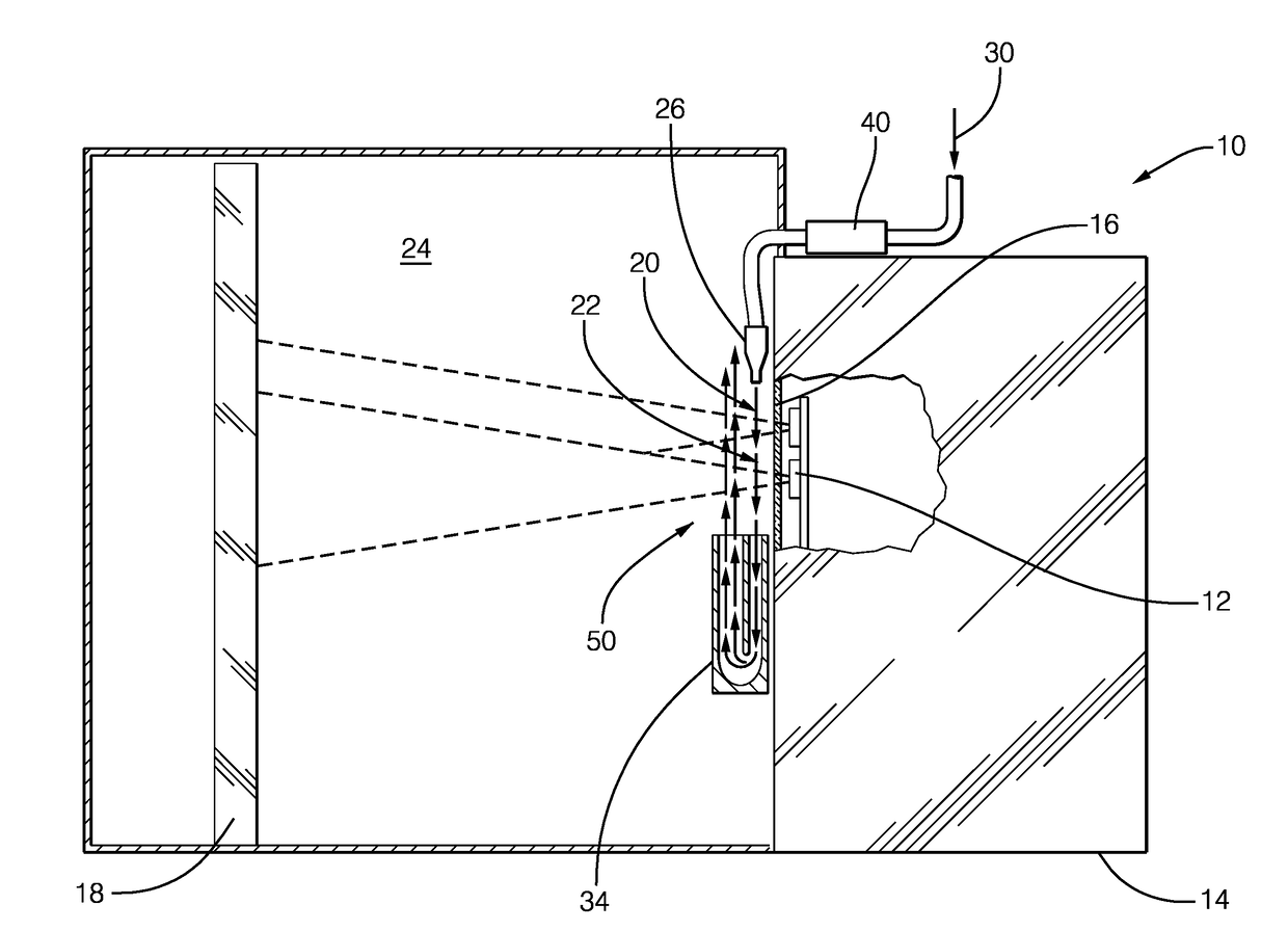
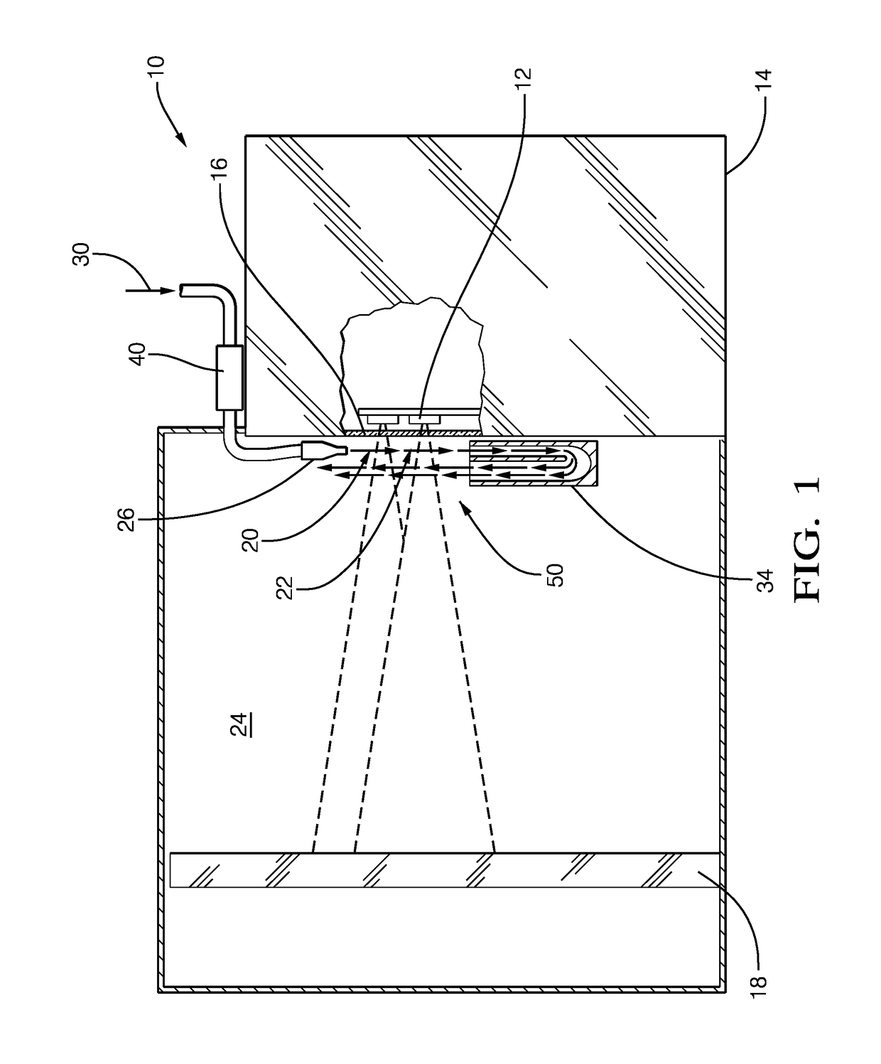
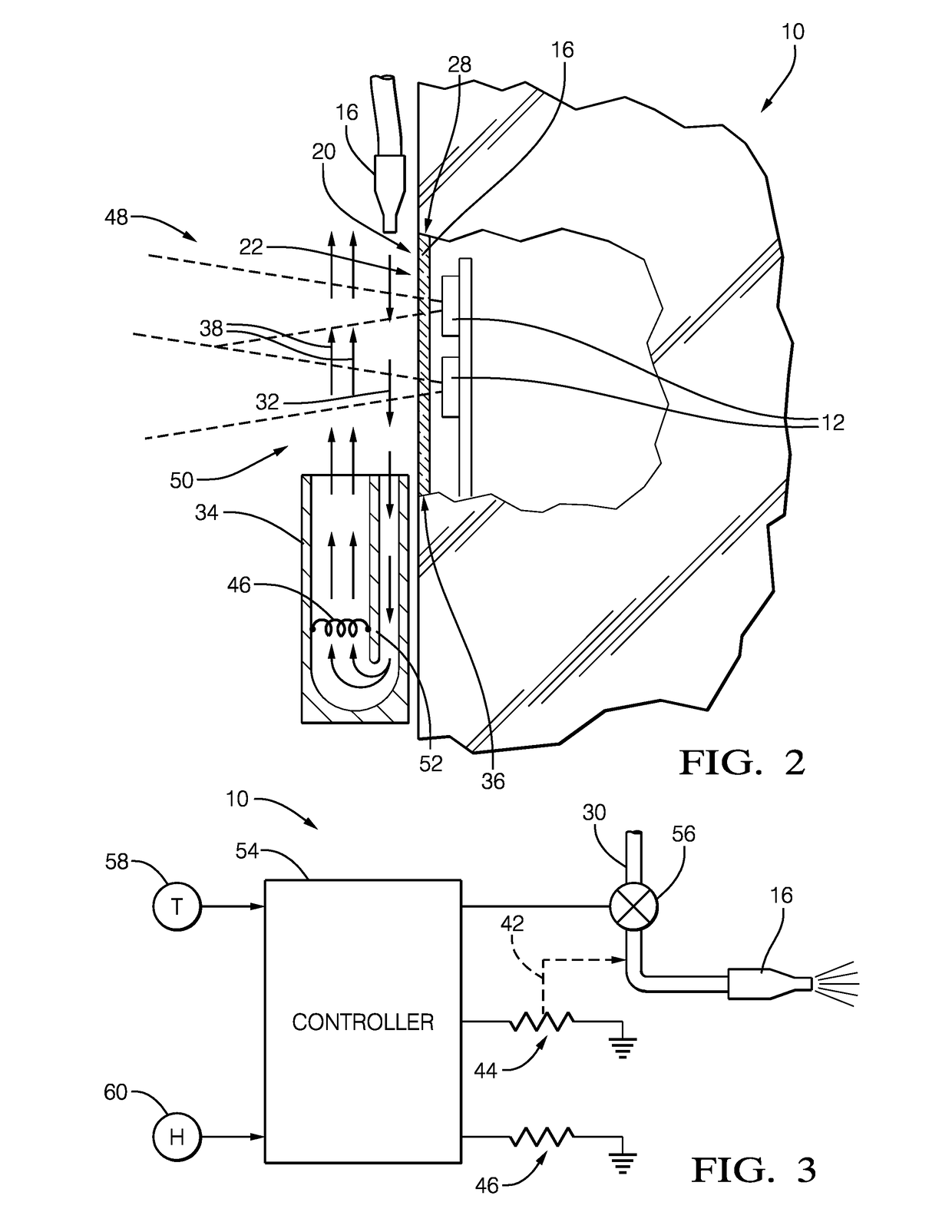
[0010]FIGS. 1 and 2 illustrate a non-limiting example of a system 10 for testing a camera 12 or multiple instances of the camera 12. While the system 10 may be suitably configured to test the camera 12 at a variety of temperatures (increased or decreased relative to ambient temperature), improvements presented herein are directed to problems that may arise while testing cameras at relatively cold temperatures. The system 10 includes a test-chamber 14 configured to establish a cold temperature (e.g. −40° C.) for testing the camera 12 within the test-chamber 14. A window 16 is installed in a wall or door of the test-chamber 14 so the camera 12 is provided with a view of a test-target 18 outside the confines of the test-chamber 14.

[0011]The window 16 preferable consists of a single-layer of transparent material rather than multiple layers which could distort the image of the test-target 18 captured or taken by the camera 12. By way of example and not limitation, the window 16 may advan...


PUM

PropertyMeasurementUnit
temperaturesaaaaaaaaaa
temperatureaaaaaaaaaa

Abstract

A cold-test system for testing a camera at a cold temperature includes a test-chamber with a window, a nozzle, and a recirculator. The window is installed in the test-chamber so the camera is provided with a view of a test-target outside of the test-chamber. The nozzle is located proximate to a first edge of the window. The nozzle is configured to direct air from an air-source in a first direction and adjacent to an outside-surface of the window. The recirculator is located proximate to a second edge of the window opposite the first edge. The recirculator is configured to receive the air moving in the first direction and re-direct that air in a second direction opposite the first direction and adjacent to the air moving in the first direction opposite the window. The nozzle and the recirculator cooperate to form a bi-directional air-curtain proximate to the outside-surface.

Description

TECHNICAL FIELD OF INVENTION[0001]This disclosure generally relates to a cold-test system for a camera, and more particularly relates to forming a bi-directional air-curtain to prevent condensation on a window of an environmental test chamber through which the camera views a test target.BACKGROUND OF INVENTION[0002]It is desired to test the operation and performance of a camera at temperatures other than ambient, e.g. cold temperatures such as −40° C. Cold testing is typically done inside an environmental test-chamber. However, the targets used to determine the operation and performance of a camera may be too large to fit inside an economically priced test-chamber. It has been suggested to place the target outside of the test-chamber and have the camera view the target through the multi-pane viewing-window that is typically provided with a test-chamber. The viewing-window is a multi-pane configuration to prevent fogging / frosting of the viewing window during cold testing. However, th...

Claims


Application Information

Patent Timeline
Patent Type & Authority Applications(United States)
IPC IPC(8): G01N17/00
CPCG01N17/002
Inventor BUGHER, ROBERT R.STOERGER, SCOTT E.BAAR, JAMES C.
Owner APTIV TECH LTD
Why Eureka
Try Eureka