Electronic component test equipment

A technology of electronic components and testing equipment, applied in the field of electronic component testing equipment, can solve the problems of cost, reduction, long pre-cooling operation time, etc.

Inactive Publication Date: 2017-01-04
HON PRECISION INC
View PDF5 Cites 7 Cited by
  • Summary
  • Abstract
  • Description
  • Claims
  • Application Information

AI Technical Summary

Problems solved by technology

[0002] Since some electronic components may be in a low-temperature environment during actual use, in order to ensure the quality of electronic components, the industry must conduct cold testing of electronic components with testing equipment after the electronic components are manufactured to eliminate defective products; please refer to figure 1 , is a schematic diagram of an electronic component testing device, which is equipped with a test device 12 and a delivery device 13 on the machine platform 11. The test device 12 is provided with a test chamber 121, and the test chamber 121 is connected to the machine platform through a delivery pipeline 122 11 an external nitrogen gas supplier (not shown), the nitrogen gas supplier transports nitrogen gas to the test chamber 121 through the delivery pipeline 122, so that the inside of the test chamber 121 is gradually cooled to the required test temperature (-40 degrees) to form A low-temperature simulated working environment, a test circuit board 123 with a test seat 124 is configured in the test chamber 121 for testing electronic components, and the conveying device 13 uses the pick-and-place device 131 as the first, second, and third directions (such as X, Y, Z direction) displacement Put the electronic component 14 to be tested into the test seat 124 of the test device 12, the test seat 124 is to carry out the cold test operation to the electronic component 14 in the low temperature simulation operation environment of the test room 121, and the test is completed Afterwards, the pick-and-place device 131 of the delivery device 13 takes out the electronic component 14 that has been tested in the test chamber 121; yet, the temperature before the electronic component 14 to be tested

Method used


Image

  • Electronic component test equipment
  • Electronic component test equipment
  • Electronic component test equipment

Examples


Embodiment Construction

[0041] In order to make your examiner further understand the present invention, hereby give a preferred embodiment and cooperate with the drawings, as follows in detail:

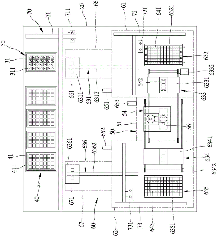
[0042] see image 3 , Figure 4 , the electronic component testing equipment of the present invention comprises machine platform 20, feeding device 30, receiving device 40, testing device 50, environment control device 60, moving device 70 and central control device (not shown), this feeding device 30 It is assembled on the machine table 20, and is provided with at least one feeding mechanism for accommodating at least one electronic component to be tested. In this embodiment, a feeding mechanism 31 with a feeding tray 311 is provided, and for The material tray 311 accommodates a plurality of electronic components to be tested; the receiving device 40 is assembled on the machine platform 20, and is provided with at least one receiving mechanism for accommodating at least one electronic component that has be...


PUM


Abstract

The invention provides electronic component test equipment, which comprises a feeding device, a receiving device, an environment control device, a test device, a moving device and a central control device. The moving device is used for taking electronic components to be tested from the feeding device and moving the electronic components to the environment control device through a material moving mechanism. The environment control device comprises at least one temporary placing area, a bearing mechanism, a temperature control mechanism and an anti-condensation mechanism. The bearing mechanism is arranged in the temporary placing area, and is used for allowing the material moving mechanism to place the electronic components to be tested with a bearer. The test device is used for taking out the pre-cooled electronic components to be tested from the bearer of the environment control device through a pickup mechanism, moving the electronic components to be tested to a test room, and placing the electronic components to be tested on a tester to carry out cold test work; and after cold test is finished, the material moving mechanism of the moving device moves the tested electronic components to the receiving device for collection. The environment control device is utilized to pre-cool the electronic components to be tested in a direct and forced manner, thereby reducing precooling work time, preventing condensation of the electronic components to ensure test qualified rate, and improving test production efficiency.

Description

technical field [0001] The invention relates to an electronic component testing equipment which can use an environmental control device to directly and forcibly pre-cool the electronic components to be tested to shorten the pre-cooling operation time, prevent condensation of the electronic components to ensure the test pass rate, and further improve the test production efficiency. Background technique [0002] Since some electronic components may be in a low-temperature environment during actual use, in order to ensure the quality of electronic components, the industry must conduct cold testing of electronic components with testing equipment after the electronic components are manufactured to eliminate defective products; please refer to figure 1 , is a schematic diagram of an electronic component testing device, which is equipped with a test device 12 and a delivery device 13 on the machine platform 11. The test device 12 is provided with a test chamber 121, and the test cha...

Claims


Application Information

Patent Timeline
IPC IPC(8): G01R1/02G01R1/04G01R31/01
Inventor 尤信超陈永宏
Owner HON PRECISION INC
Why Eureka
Try Eureka