High and low temperature test equipment

a high and low temperature test equipment technology, applied in static indicating devices, instruments, optics, etc., can solve the problems of increasing production costs, low heating efficiency and heat uniformity of high temperature test equipment, and discharging of heat generated by low temperature test equipment during cooling. achieve the effect of improving heat uniformity and saving energy

Active Publication Date: 2014-06-05
BOE TECH GRP CO LTD +1
View PDF2 Cites 7 Cited by
  • Summary
  • Abstract
  • Description
  • Claims
  • Application Information

AI Technical Summary

Benefits of technology

[0007]In view of the above disadvantages in the conventional art, an object of the Invention is to provide a high and low temp

Problems solved by technology

1. The high and low temperature test equipments are separated, which results in that the heat generated by the low temperature test equipment during cooling is dissipated, while the heating efficiency and heat uniformity of the high temperature test equipment are low. Moreover, the liquid crystal panel has to be moved or shifted to

Method used


Image

  • High and low temperature test equipment
  • High and low temperature test equipment
  • High and low temperature test equipment

Examples


embodiment 1

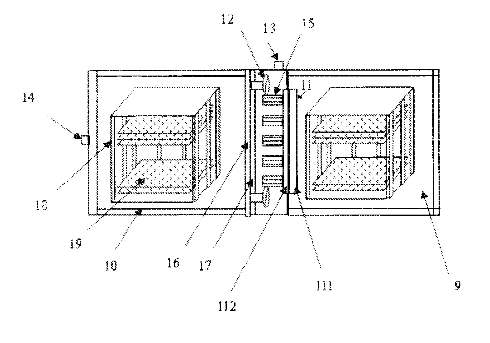
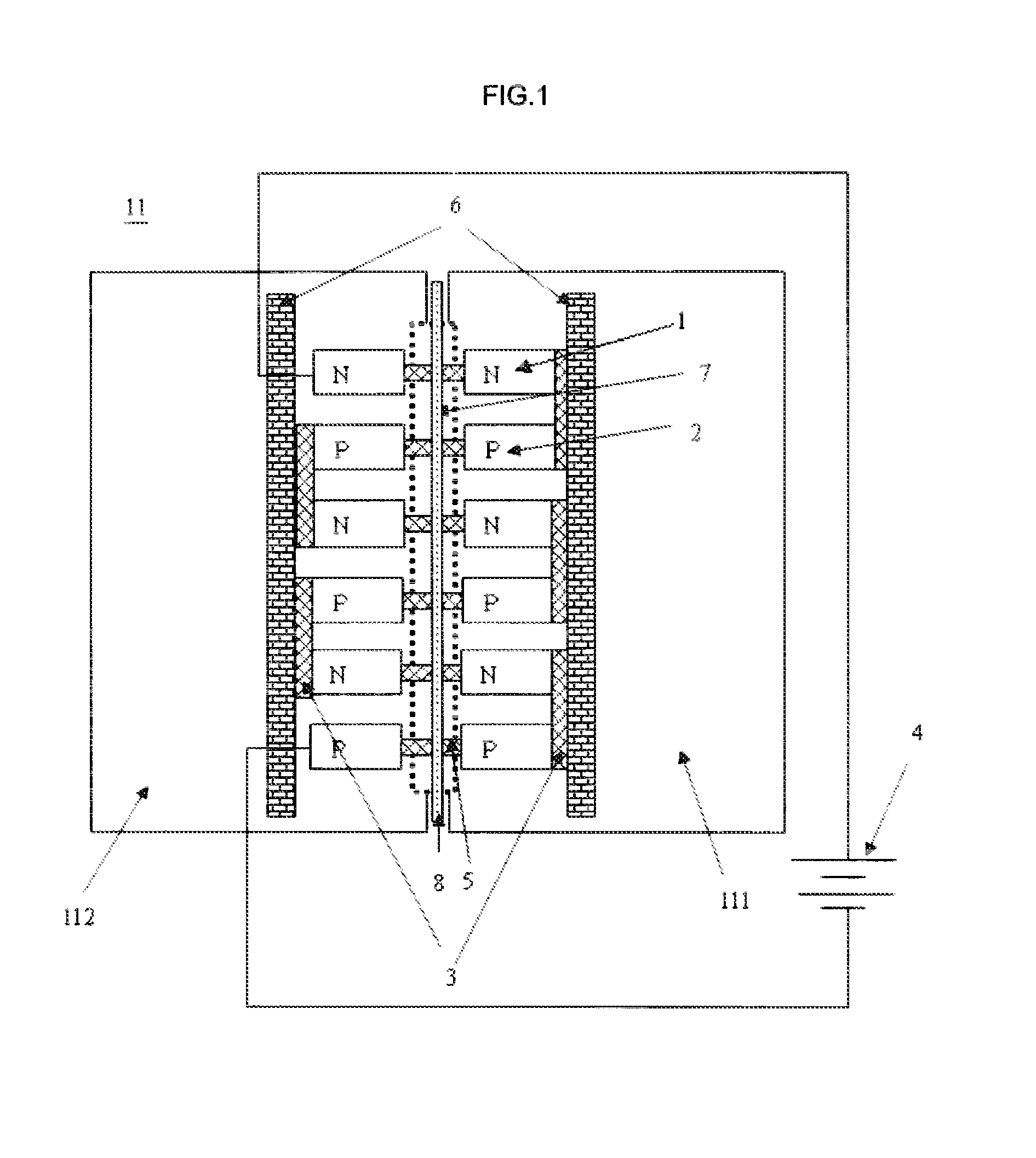
[0035]In the following, the invention will be described in connection with the drawings and with reference to an example of the embodiment 1, wherein the housing is divided by the partition into a first chamber and a second chamber separated from each other. In the embodiment, the first chamber is a cooling chamber 9, the second chamber is a heating chamber 10, and a Peltier effect sheet 11 is disposed on a partition 8. As illustrated in FIGS. 1 and 2, the Peltier effect sheet 11 is disposed between the cooling chamber 9 and the heating chamber 10. The Peltier effect sheet 11 has a cooling side 111 and a heating side 112, where the cooling side 111 is disposed in the cooling chamber 9 and adapted for providing cooling capacity to the cooling chamber 9, while the heating side 112 is disposed in the heating chamber 10 and adapted for providing heating capacity to the heating chamber 10. The Peltier effect sheet 11 may be monolithically disposed on the partition 8 or be divided into a ...

embodiment 2

[0060]The embodiment differs from Embodiment 1 in that the high and low temperature test equipment does not comprise the first and second temperature acquiring units. That is, the embodiment does not comprise the first to the fourth temperature sensors.

[0061]In the embodiment, the temperatures in the cooling chamber 9 and the heating chamber 10 may be acquired by manually measuring via a thermometer. Alternatively, a thermometer may be placed in the cooling chamber 9 or the heating chamber 10 in advance and then read by a person to obtain the temperatures.

[0062]The other components in the high and low temperature test equipment of the embodiment are the same as those in Embodiment 1 and will not be elaborated here. In addition to the advantages of Embodiment 1, the high and low temperature test equipment according to the embodiment may further reduce the structural complexity and volume of the equipment as well as the manufacture cost.

embodiment 3

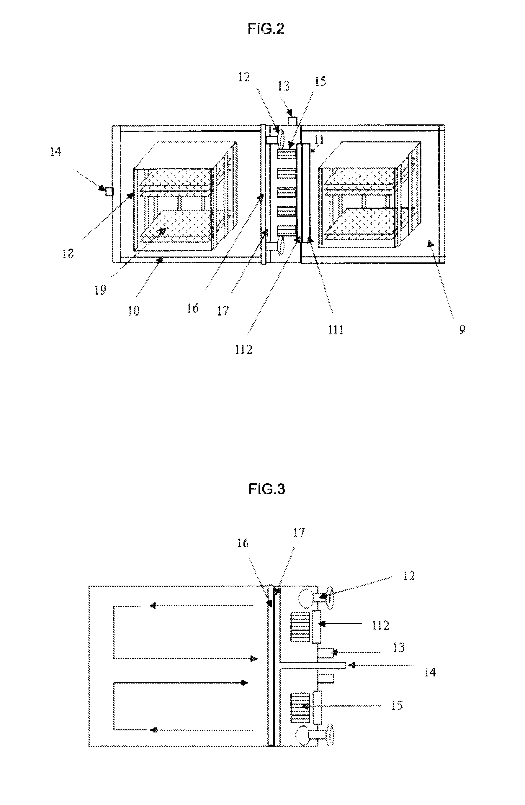
[0063]The embodiment differs from Embodiment 1 in that the air convection unit in the heating chamber 10 of the high and low temperature test equipment employs a dual cycle mode. In comparison with the single cycle mode of Embodiment 1, the dual cycle mode of the embodiment may guarantee a more uniform heat distribution in the heating chamber 10, more stable temperature and more accurate result of the high temperature test.

[0064]As Illustrate in FIG. 3, in the dual cycle heating chamber 10, there are two inlets 13 with Inlet valves (not shown in FIG. 3) accordingly disposed therein, while only one outlet 14 is needed, which also has an outlet valve (not shown in FIG. 3) disposed therein. The two inlets 13 and the corresponding inlet valves, the outlet 14 and the corresponding outlet valve are disposed on the same side wall of the heating chamber 10. Preferably, the two inlets 13 are disposed on both sides of the outlet 14 respectively. In this way, air carrying the heat and blown in...


PUM


Abstract

The invention relates to the technical field of LDC fabrication and specifically to a high and low temperature test equipment. The high and low temperature test equipment comprises a housing, and further comprises a partition disposed in the interior of the housing. The partition divides the interior of the housing into a plurality of chambers and is provided with a Peltier effect sheet. The Peltier effect sheet is used for, when it is powered-on, cooling at least one of the chambers and meanwhile heating at least one chamber other than the at least one of the chambers. The high and low temperature test equipment may cool and heat at the same time in an efficient, power conserving way and have uniform heating function.

Description

FIELD OF THE INVENTION[0001]The present invention relates to LCD fabrication technologies, more particularly, to a high and low temperature test equipment.BACKGROUND OF THE INVENTION[0002]A substance may exhibit different temperature characteristics and have different properties at different temperatures. In this sense, to ensure qualified performance of a substance or a product using the substance under different ambient temperatures, a high and low temperature test will be performed on the finished product to ensure the product quality.[0003]A liquid crystal panel is a critical component of a liquid crystal display (LCD). Liquid crystals are filled in the liquid crystal panel, and the property of the liquid crystals plays an important role in determining the performance of the liquid crystal panel. Currently, the high and low temperature test on the liquid crystal panel is generally conducted by placing the liquid crystal panel in a high temperature chamber and a low temperature c...

Claims


Application Information

Patent Timeline
IPC IPC(8): G01N25/00
CPCG01R31/2817G02F1/1309G09G3/006G09G3/36G09G2320/041
Inventor JING, YANGKUN
Owner BOE TECH GRP CO LTD
Why Eureka
Try Eureka