Method for desulfurizing hydrocarbon fractions from steam cracking effluents

a technology of hydrocarbon fractions and effluents, which is applied in the direction of hydrocarbon oil treatment products, metal/metal-oxide/metal-hydroxide catalysts, physical/chemical process catalysts, etc., can solve the problems of significant additional investment, inability to use without additional treatment, and incompatible sulfur content with the evolution of standards, etc., to limit the heat release, limit the temperature gradient in the reactor, and avoid the effect of reaching

Active Publication Date: 2008-09-18
INST FR DU PETROLE
View PDF9 Cites 10 Cited by
  • Summary
  • Abstract
  • Description
  • Claims
  • Application Information

AI Technical Summary

Benefits of technology

[0056]In parallel with the sulfur compound alkylation reactions, olefins dimerization reactions may occur in the reactor, involving weighting of the hydrocarbon fraction treated. However, the aromatic type compounds are hardly or even not converted in the reactor. Generally, aromatics conversion is below 10%, preferably below 5%, which allows to preserve the octane number of the cut. The sulfur compound alkylation and olefin dimerization reactions have an exothermic character, i.e. they are favoured at low temperature and they release heat. In order to limit the heat release and not to reach excessive temperatures in the reactor, it can be advantageous to recycle a fraction of the effluent(s) of the reactor(s) to the inlet of the reactor(s). The recycle ratio, defined as the flow rate of recycled effluent divided by the flow rate of fresh feed, typically ranges between 0.2 and 4, preferably between 0.5 and 2.
[0057]In the particular case where the catalyst used is an ion-exchanging resin, it can be advantageous to use the catalyst in a so-called expanded bed. The feed is therefore generally injected into the reactor bottom, at a sufficient linear velocity to cause suspension of the catalyst balls. This type of implementation affords the advantage of limiting the temperature gradient in the reactor, i.e. the temperature difference between the outlet and the inlet of the reactor, and of providing good distribution of the liquid hydrocarbon feed and good thermal homogeneity in the reactor.
[0058]According to a preferred embodiment, a catalyst addition / withdrawal system can be added to the reactor in order to achieve continuous withdrawal of the used catalyst and to have fresh catalyst makeup.

Problems solved by technology

In fact, these gasolines contain about 300 ppm weight of sulfur, as well as high reactive unsaturated compound contents, which makes them unusable without an additional treatment.
However, their sulfur content becomes incompatible with the evolution of the standards relative to the maximum sulfur content of gasolines that tend to fall below 50 ppm, or 30 ppm, or even 10 ppm weight.
These first two options lead to notable additional investments and hydrogen consumption, a gas that becomes increasingly rare on refining and petrochemistry sites, without any gain as regards valorization of the products that remain gasoline bases of rather poor quality.
Furthermore, deep desulfurization is accompanied by a limited reduction in the aromatics content to be minimized, which remains unfavourable for the octane number and therefore for its valorization.
This option leads to a significant depreciation of the price of the gasoline thus sold.
However, the existing solutions or those considered exclusively consist in carrying out hydrodesulfurization stages that require the presence of hydrogen in a costly process and they do not describe the possibility of treating one of the fractions from the steam cracking plant by means of a process based on weighting the sulfur compounds on an acid catalyst.

Method used


Image

  • Method for desulfurizing hydrocarbon fractions from steam cracking effluents
  • Method for desulfurizing hydrocarbon fractions from steam cracking effluents
  • Method for desulfurizing hydrocarbon fractions from steam cracking effluents

Examples


examples

[0073]The following example describes in a non limitative way catalysts and operating conditions that can be used in the method according to the invention.

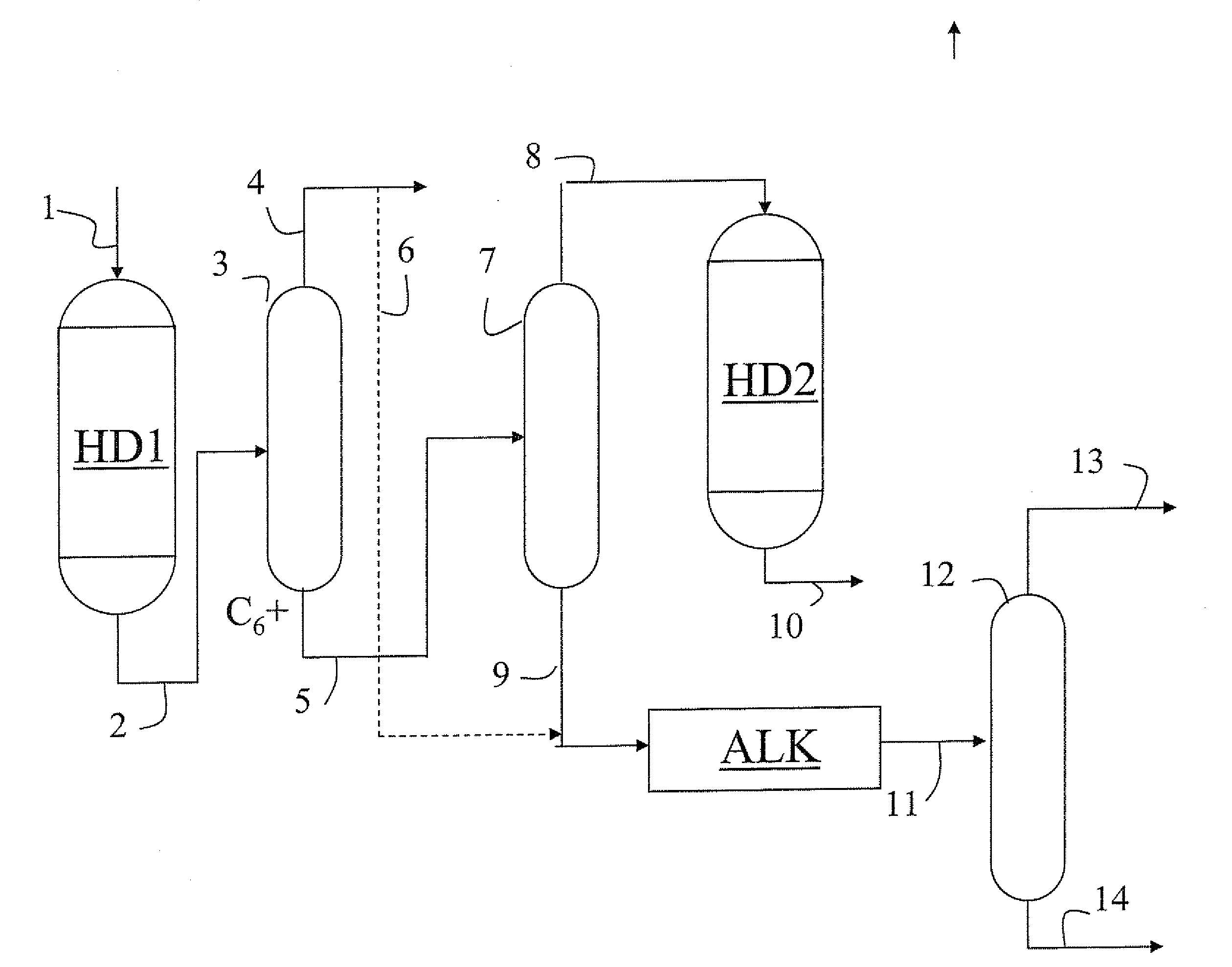
[0074]Naphtha steam cracking effluents are fractionated in an effluent treating plant, comprising primary distillation, so as to produce notably a pyrolysis gasoline cut α, comprising essentially C5 and heavier hydrocarbons up to an ASTM end point of 210° C.

[0075]This pyrolysis gasoline cut α has the following characteristics:[0076]Sulfur content: 200 ppm weight[0077]Composition of the pyrolysis gasoline cut α (wt. %)

C3C4C5C6C7C8C9C10C11C12+Totaln-paraffins0.00.13.61.30.20.00.00.00.00.05.2i-paraffins0.02.71.40.30.40.10.00.00.04.9mono-olefins0.20.65.31.70.71.00.40.31.00.912.1diolefins0.01.110.33.93.41.80.120.8naphthenes0.51.30.50.10.00.00.00.02.5aromatics26.611.84.22.01.90.70.147.3alkenyl3.53.10.50.00.07.1aromaticsTotal0.21.822.436.413.59.25.66.23.61.1100.0

[0078]This pyrolysis gasoline cut is treated according to the process layout...


PUM

PropertyMeasurementUnit
boiling point temperatureaaaaaaaaaa
pressureaaaaaaaaaa

Abstract

The present invention relates to a method for treating a feed corresponding to a pyrolysis gasoline, comprising:
    • a) at least one stage of selective hydrogenation of the feed, referred to as HD1,
    • b) fractionating in one or more distillation columns the effluent from stage a) in order to produce at least one light C5 cut, an intermediate C6 or C6-C7 or C6-C8 cut intended for aromatics production, a heavy C7+ or C8+ or C9+ cut intended for gasoline production,
    • c) at least one stage of hydrodesulfurization and deep hydrogenation of the intermediate cut, referred to as HD2,
    • d) at least one stage of alkylation of the heavy C7+, C8+ or C9+ cut consisting of a treatment on an acid catalyst allowing weighting of the sulfur compounds,
    • e) at least one stage of distillation of the effluent from stage d), intended to produce a light fraction that can be directly used as a low-sulfur gasoline base, and a heavy C11+ or C12+ fraction rich in sulfur compounds, used as middle distillate or fuel oil.

Description

FIELD OF THE INVENTION[0001]The present invention relates to a method for treating hydrocarbon steam cracking effluents. The steam cracking process is a known petrochemical process at the root of the production of the building-block chemicals, in particular ethylene and propylene. Steam cracking produces, apart from ethylene and propylene, large amounts of less valorizable coproducts, notably aromatic pyrolysis gasoline that is obtained in significant proportions when cracking propane or butane, and even more when cracking naphtha, gas oil or condensates.BACKGROUND OF THE INVENTION[0002]Raw pyrolysis gasoline is often hydrogenated in two stages, with intermediate fractionation so as to typically produce a C5 cut, various cuts intended to produce aromatic bases and gasoline bases or fuel oil. The existing process layouts generally allow to produce a C6 cut to extract benzene and a C7+ cut or a C6-C7-C8 cut to extract benzene, toluene and xylenes, and a C9+ cut.[0003]By definition, a ...

Claims


Application Information

Patent Timeline
Patent Type & Authority Applications(United States)
IPC IPC(8): C10G45/32
CPCC10G29/205C10G45/32C10G2400/02C10G69/123C10G69/14C10G45/40C10G67/08
Inventor PICARD, FLORENTDEBUISSCHERT, QUENTINPUCCI, ANNICK
Owner INST FR DU PETROLE
Why Eureka
Try Eureka