
Apparatus And Methods For Making Analyte Particles

Inactive Publication Date: 2011-05-26
WATERS TECH CORP
View PDF16 Cites 9 Cited by
  • Summary
  • Abstract
  • Description
  • Claims
  • Application Information

AI Technical Summary

Benefits of technology

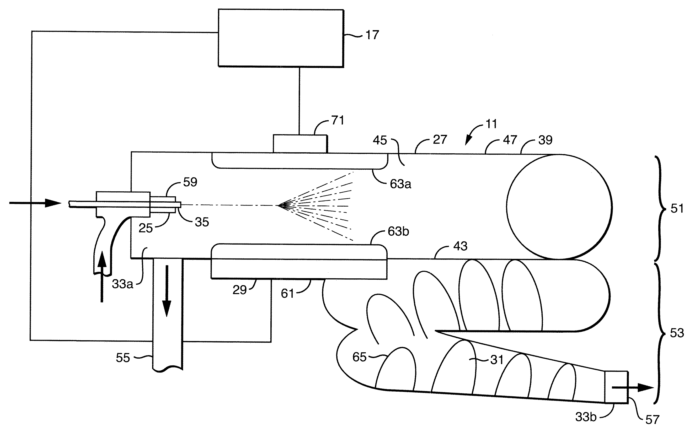
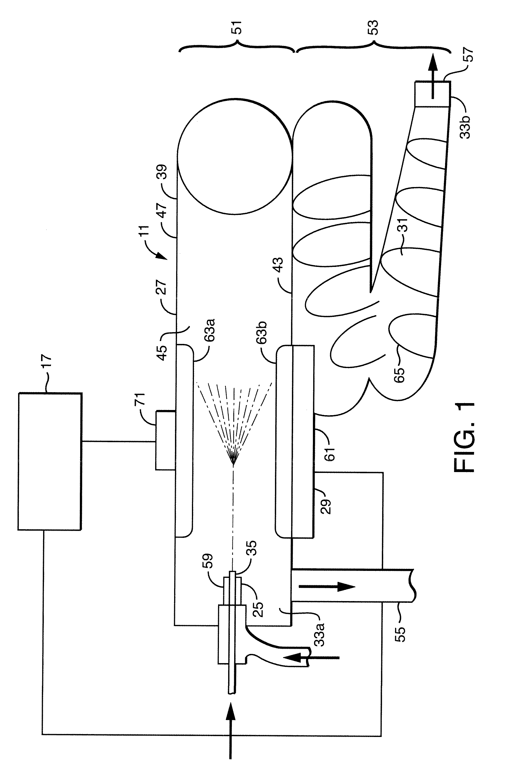
[0014]Embodiments of the present apparatus are particularly suited for placing the nebulizer in communication with a liquid chromatography system. The device of the present invention can rapidly and efficiently remove a large volume of liquid from the plume that condenses. Removal of condensed waste is facilitated with the waste port at a low point or bottom of the chamber. And, preferably, the waste port is located at the nebulization section.
[0022]A preferred vessel is a cylindrical or elongated conical in shape having a first end and a second end. In conical forms the ends comprise the base and tip. The nebulization section is at one of said first end and second end and the desolvation section is at said remaining end. A preferred vessel has at least one of said nebulization section and said desolvation section coiled. Coiling allows the vessel to be more conveniently sized and improves thermal uniformity. A preferred vessel has a nebulization section having a larger diameter than the diameter of the desolvation section in order to contain the plume and waste.

Problems solved by technology

It is difficult to couple chromatography techniques with condensation nucleation light scattering detection due to the volume of liquid generated by HPLC separation.

Method used


Image

  • Apparatus And Methods For Making Analyte Particles
  • Apparatus And Methods For Making Analyte Particles
  • Apparatus And Methods For Making Analyte Particles

Examples


Embodiment Construction

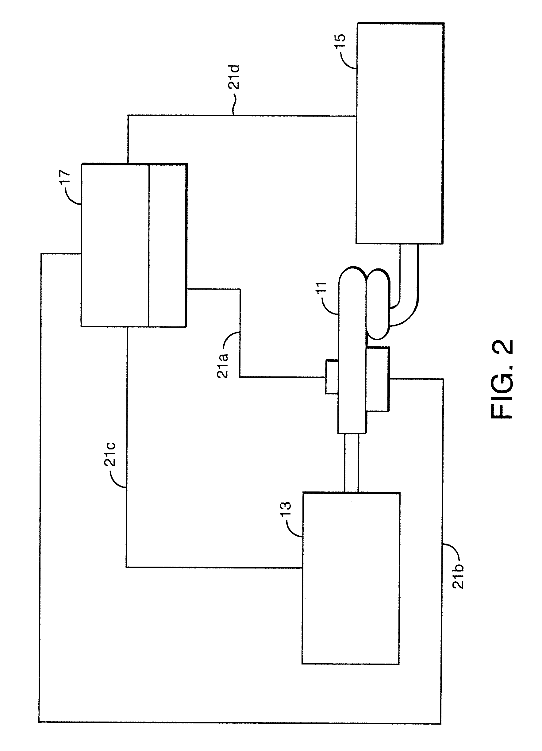
[0031]Embodiments of the present invention will be described in detail as methods and apparatus for forming analyte particles for condensation nucleation for use in light scattering detection from samples originating from a liquid chromatograph. However, embodiments of the present invention have application in other techniques as well. For example, the apparatus can be used without a liquid chromatograph or without a condensation nucleation apparatus, or it may be used in conjunction with other particle detection devices including those that use electrical means for detection such as the CoronaCad sold by ESA Biosciences of Chelmsford, Mass.

[0032]Turning now to FIG. 1, a device for making particulate analyte molecules, generally designated by numeral 11, is depicted. The device makes analyte particles for condensation nucleation light scattering detection. The analyte molecules are potentially present in solution or suspension in a liquid sample having solvent.

[0033]Turning briefly ...


PUM


Abstract

A device for making particulate analyte molecules comprising a nebulizer producing a plume of liquid droplets, a vessel having a chamber to receive the plume in which the chamber has a nebulization section, a desolvation section. The nebulization section is cooled to form a condensed waste from a portion of said plume. The desolvation section is heated to form solvent gas molecules and particulate analyte molecules.

Description

CROSS-REFERENCE TO RELATED APPLICATIONS[0001]The application claims priority to U.S. Provisional Patent Application No. 61 / 037,893, filed Mar. 19, 2008, the entire contents of which are incorporated herein by reference.STATEMENT REGARDING FEDERALLY SPONSORED RESEARCH OR DEVELOPMENT[0002]None.THE NAMES OF THE PARTIES TO A JOINT RESEARCH AGREEMENT[0003]None.REFERENCE TO SEQUENCE LISTING[0004]None.BACKGROUND[0005]To facilitate an understanding of the present invention, certain words and phrases will be defined. An “analyte” is a compound that is of interest in the sense that one desires to detect its presence or absence or the quantity in a sample. The term “sample” is used in a broad sense to denote any material, solution, mixture, compound, whether gas, liquid or solid that one may wish to investigate. Samples may be of biological or non-biological in origin. Biological samples may comprise tissues or fluids.[0006]Evaporative processes are those in which a liquid undergoes a phase tr...

Claims


Application Information

Patent Timeline
IPC IPC(8): B05B1/24
CPCG01N30/74G01N30/84G01N2030/847G01N21/47
Inventor JARRELL, JOSEPH A.
Owner WATERS TECH CORP
Learn More