Fluorescent LED backlight plate assembly

a technology of led backlight plate and led backlight plate, which is applied in the direction of optical light guide, instruments, optics, etc., can solve the problems of not meeting the requirements of high resolution tv, being used in daytime, and the intensity and saturation of red and green lights have bad qualities, so as to achieve strong and saturated, high intensities, and high saturation

Inactive Publication Date: 2017-06-15
WU CHIH WEI
View PDF10 Cites 0 Cited by
  • Summary
  • Abstract
  • Description
  • Claims
  • Application Information

AI Technical Summary

Benefits of technology

[0004]To improved above mentioned defects in the prior art, the present invention provides a fluorescent LED backlight plate assembly, wherein a fluorescent plate is added to the LED backlight plate, which can be added to an upper side of the light guide plate or any light processing plate in the light processing module. The LED light source in the LED light bar is blue light source. The fluorescent material contains green and red fluorescent materials. When light from the LED light bar passed through the fluorescent materials, the fluorescent materials will be stimulated so as to emit red and green lights which are stronger and saturated. Then these red and green lights pass through an LED panel, they still retain high intensities and high saturations so as to present colors of high quality. As a result, the image on the panel has high resolution and the image is clear in daytime. Therefore, the conventional problem of low light intensities and low saturation in the conventional LCD panels are improved.
[0005]For achieve above object, the present invention provides a fluorescent LED backlight plate assembly at least one LED bar containing a plurality of LED light sources which includes blue LED light source; a light guide plate aside the LED light bar; light emitted from the LED light bar will be incident into the light guide plate and transferring along a surface of the light guide plate. a light reflecting sheet below the light guide plate; light dispersed from the light guide plate being reflected by the light reflecting sheet to be incident upwards; a light processing module located above the light guide plate; the light processing module containing a plurality of light processing plates for further processing the light from or passing through the light guide plate; and a fluorescent plate containing green and red fluorescent material for presenting yellow color; wherein when red fluorescent and green fluorescent materials are stimulated, they emit red light and green light, so that light intensity directly from the fluorescent plate is stronger and thus, when these light further passes through an LCD panel, they will present high light intensity and saturation.

Problems solved by technology

Thus when these lights further pass through an LCD panel, intensities and saturations of red and green lights have bad qualities.
They cannot achieve requirements of high resolution TVs and being used in daytime.

Method used


Image

  • Fluorescent LED backlight plate assembly
  • Fluorescent LED backlight plate assembly
  • Fluorescent LED backlight plate assembly

Examples


first embodiment

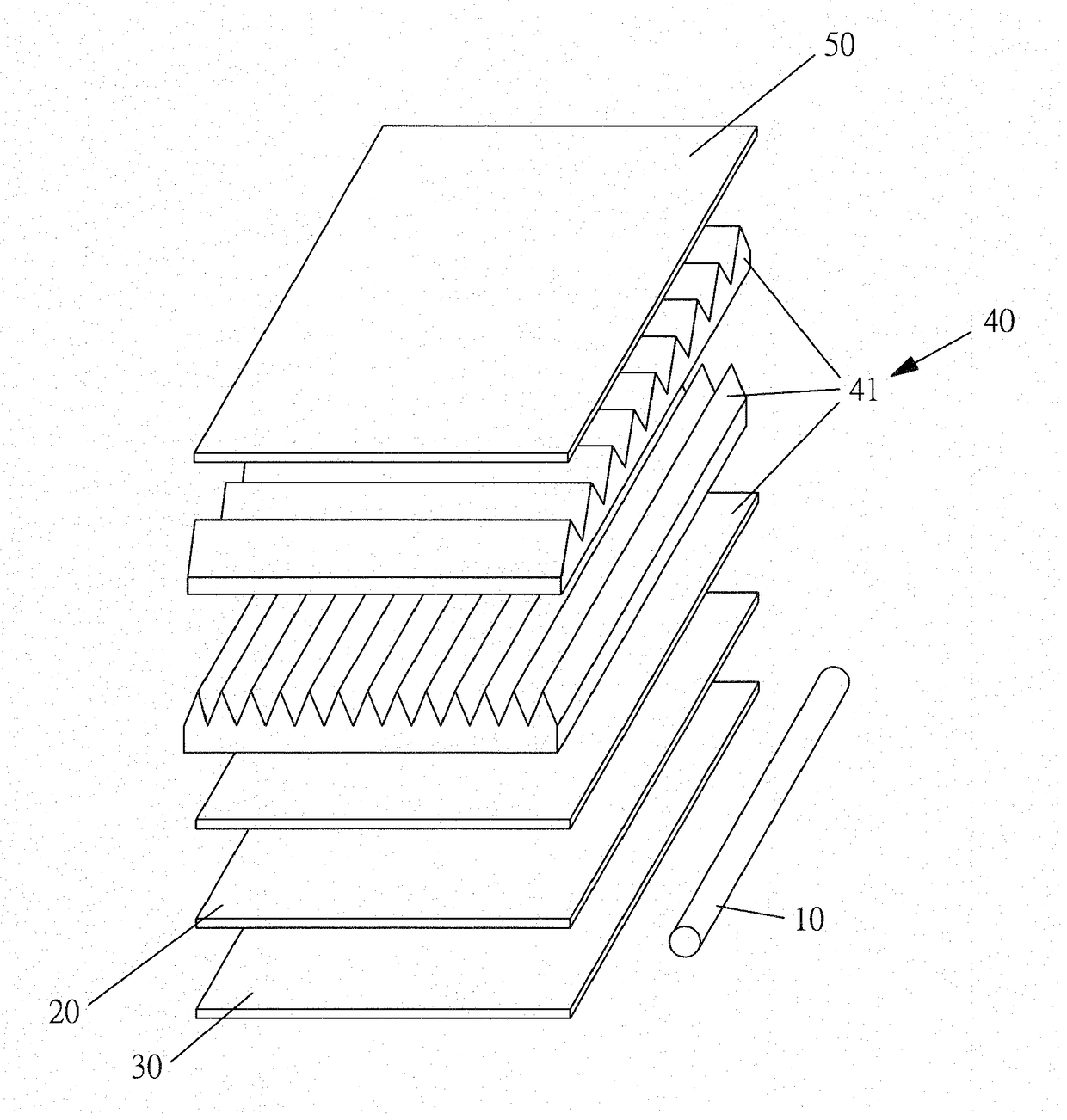
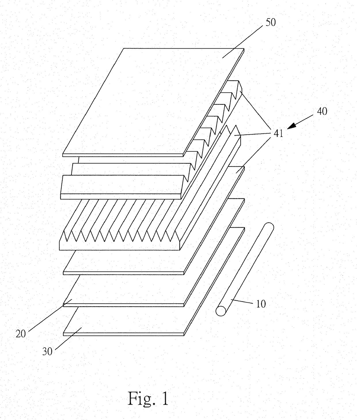
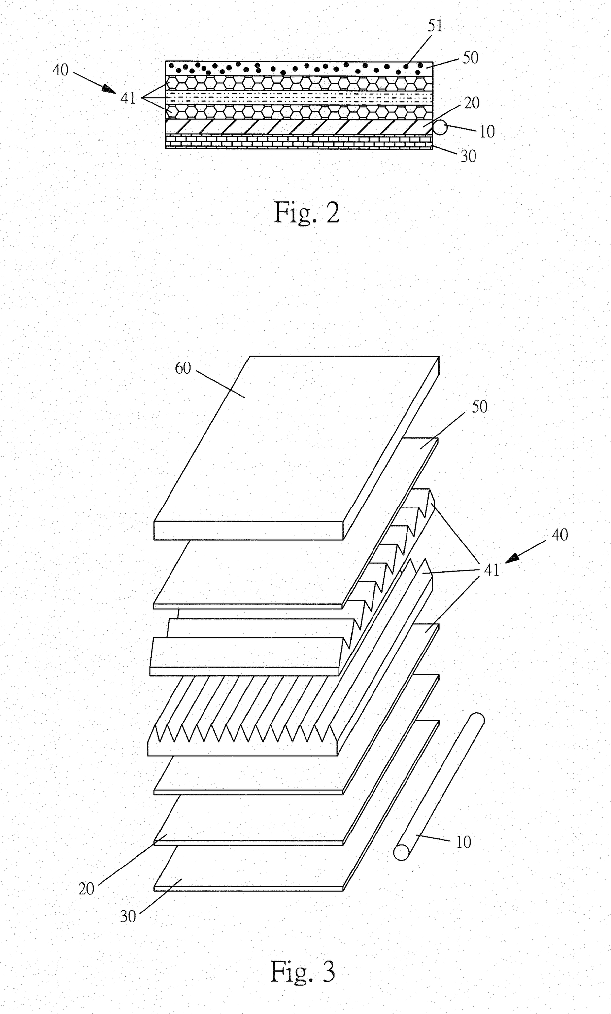
[0015]With reference to FIGS. 1 to 4, he present invention will be described herein. The LED backlight plate containing fluorescent materials of the present invention has the following elements.

[0016]At least one LED bar 10 contains a plurality of LED light sources which includes blue LED light source.

[0017]A light guide plate is aside the LED light bar. Light emitted from the LED light bar will be incident into the light guide plate and transfers along the surface of the light guide plate. In one application, a side of the light guide plate near the LED light bar may be textured for concentrating light from the LED light bar.

[0018]A light reflecting sheet 30 is below the light guide plate 20. Light dispersed from the light guide plate 20 will be reflected by the light reflecting sheet 30 to be incident upwards.

[0019]A light processing module 40 is located above the light guide plate 20. The light processing module 40 contains a plurality of light processing plates 41 for further pr...

second embodiment

[0026]In the second embodiment, the backlight plate of the present invention comprises:

[0027]At least one LED bar 10 contains a plurality of LED light sources which includes blue LED light source.

[0028]A light guide plate 20 is aside the LED light bar 10. Light emitted from the LED light bar 10 will be incident into the light guide plate 20 and transfers along the surface of the light guide plate 20. In one application, a side of the light guide plate 20 near the LED light bar 10 may be textured for concentrating light from the LED light bar 10.

[0029]A light reflecting sheet 30 is below the light guide plate 20. Light dispersed from the light guide plate 20 will be reflected by the light reflecting sheet 30 to be incident upwards.

[0030]A light processing module 40 is located above the light guide plate 20. The light processing module 40 contains a plurality of light processing plates 41 for further processing the light from or passing through the light guide plate 20 so that the lig...


PUM


Abstract

A fluorescent LED backlight plate assembly includes: at least one LED bar containing blue LED light sources; a light guide plate aside the LED light bar; a light reflecting sheet below the light guide plate; a light processing module located above the light guide plate; the light processing module containing a plurality of light processing plates and a fluorescent plate containing green and red fluorescent material. When red fluorescent and green fluorescent materials are stimulated, they emit red and green lights, so that light intensity is enhanced. Thus, when these light further passes through an LCD panel, they will present high light intensity and saturation. In another embodiment, no fluorescent plate is used, while fluorescent materials are added to the light guide plate or the light processing plates. The fluorescent materials contain red and green fluorescent materials.

Description

FIELD OF THE INVENTION[0001]The present invention relates to LED backlight plates; and in particular to a fluorescent LED backlight plate assembly.BACKGROUND OF THE INVENTION[0002]A conventional LED backlight plate mainly contains at least one LED light bar, a light guide plate, a light reflecting sheet and a light processing module. The LED light bar comprises a plurality of LED light sources for light emission. The light guide plate is located aside the LED light bar for receiving light from the LED light bar and thus guiding the light along a surface of the light guide plate. The LED light bar is below the light guide plate for reflecting light from the light guide plate and then passes through the light guide plate to be transferred upwards. A light processing module is at an upper side of the light guide plate. The light processing module comprises a plurality of light processing plates for processing light from the light guide plate towards the light processing module so as to...

Claims


Application Information

Patent Timeline
Patent Type & Authority Applications(United States)
IPC IPC(8): F21V8/00
CPCG02B6/005G02B6/0068G02B6/0055G02B6/0003
Inventor WU, CHIH-WEI
Owner WU CHIH WEI
Why Eureka
Try Eureka