Camera module and method for manufacturing camera module
a technology of camera modules and camera bodies, applied in the field of camera modules, can solve the problems of increasing the risk of suspension wire b>102/b> fracturing and insufficient prevention and achieve the effect of reducing the risk of suspension wire fracturing
- Summary
- Abstract
- Description
- Claims
- Application Information
AI Technical Summary
Benefits of technology
Problems solved by technology
Method used
Image

Examples
embodiment 1
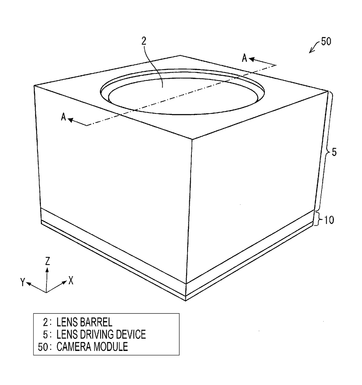
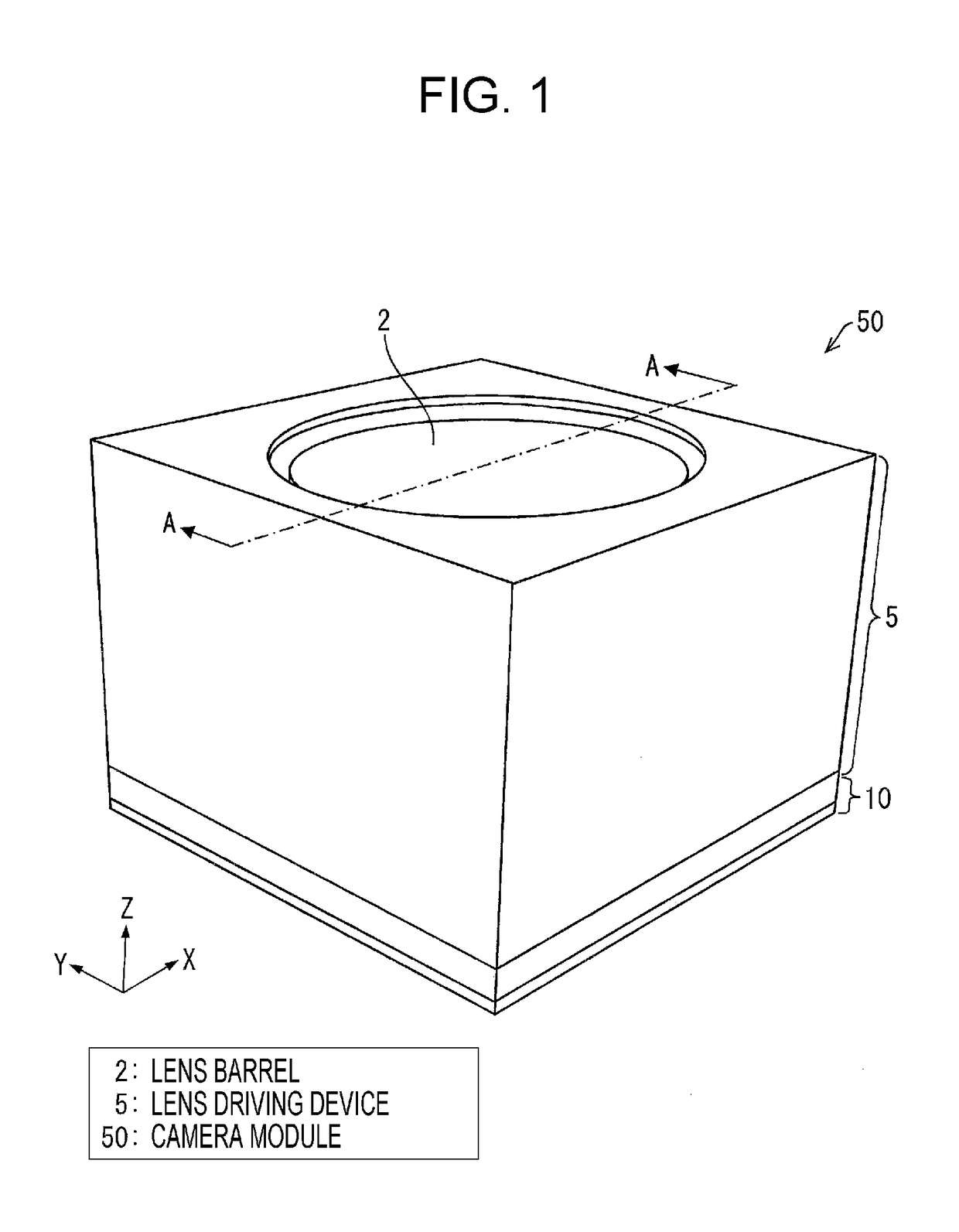
[0027]FIG. 1 is a perspective view that schematically illustrates an outline configuration of a camera module 50 of the present embodiment. Additionally, the XYZ axes illustrated in FIG. 1 correspond to the coordinate system axis of FIG. 2 to FIG. 10.
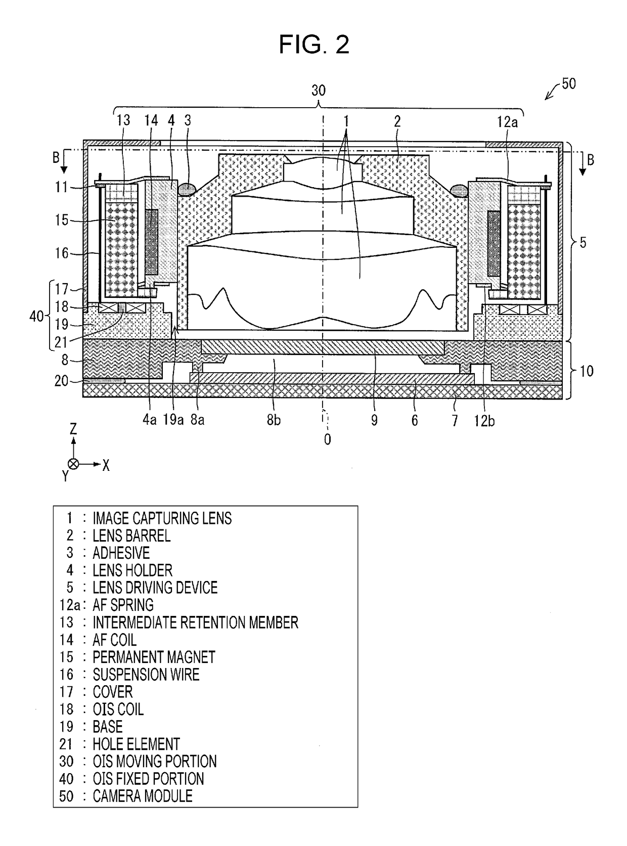
[0028]FIG. 2 is a cross-sectional view that illustrates a configuration of the camera module 50 illustrated in FIG. 1. Additionally, FIG. 2 is a cross-sectional view taken along line A-A in FIG. 1.
[0029]FIG. 3 is another cross-sectional view that illustrates configuration of the camera module 50 illustrated in FIG. 1. Additionally, FIG. 3(a) is a cross-sectional view taken along line B-B in FIG. 2. In addition, FIG. 3(b) is an enlarged view of a main portion C illustrated in FIG. 3(a).
[0030]FIG. 4 is cross-sectional views that illustrate configurations that prevent a suspension wire 16 of the camera module 50 illustrated in FIG. 1 from fracturing, (a) illustrates a state in which force is not applied to the suspension wire 16, and (b) i...
second embodiment
[0068]The second embodiment differs from the first embodiment in that the arm portion 12c, and in particular, the shape of the flexible portions 12d is different. FIG. 7(a) is a view that illustrates a configuration that prevents the suspension wire 16 in the camera module 50 of the present embodiment from fracturing, corresponds to FIG. 3(b), and is an enlarged view of the vicinity of the of a connection portion of the suspension wire 16 and the arm portion 12c, which is on an outer side of the AF spring in the camera module 50. Additionally, the same member numbers are given to the same members as those of the first embodiment, and detailed description thereof will be omitted.
[0069]As illustrated in FIG. 7, in the second embodiment, the shape of the flexible portions 12d is a shape that includes meander portions 12D. In contrast to the first embodiment having ring-shaped flexible portions, as a result of setting a meander structure in the manner of the second embodiment, it is pos...
modification examples
[0071]FIGS. 7(b) and 7(c) are views that illustrate modification examples of the configuration that prevent the suspension wire 16 illustrated in FIG. 7(a) from fracturing. FIG. 7(c) is a side view with respect to FIG. 7(b) when the shape of the meander portions 12D of the flexible portions 12d illustrated in FIG. 7(b) is viewed from a side surface side (a y axis direction side) with respect to a direction (a direction in Zx plane) in which the meander portions 12D extend.
[0072]As illustrated in FIG. 7(a), the meander portions 12D are not limited to a shape that extends on an XY plane. For example, as illustrated in FIGS. 7(b) and 7(c), a shape that extends on the Zx plane may be used. Additionally, an xyZ coordinate system axis is a coordinate system axis in which the XYZ axes are rotated with the Z axis serving as the center axis, an x axis is parallel to the axis 22b, and a y axis is parallel to the axis 22a.
[0073]Further, the meander portion 12D illustrated in FIGS. 7(b) and 7(...
PUM
 Abstract
Description
Claims
Application Information
 - R&D Engineer
- R&D Manager
- IP Professional
- Industry Leading Data Capabilities
- Powerful AI technology
- Patent DNA Extraction
Browse by: Latest US Patents, China's latest patents, Technical Efficacy Thesaurus, Application Domain, Technology Topic.
© 2024 PatSnap. All rights reserved.Legal|Privacy policy|Modern Slavery Act Transparency Statement|Sitemap