Stent

a stent and vascular wall technology, applied in the field of stents, can solve the problems of no other options and high risk of fracture, and achieve the effects of reducing the risk of injury, improving the application of inventive stents, and reducing the trauma to the vascular wall

Active Publication Date: 2010-01-12
QUALIMED INNOVATIVE MEDIZINPROD
View PDF17 Cites 10 Cited by
  • Summary
  • Abstract
  • Description
  • Claims
  • Application Information

AI Technical Summary

Benefits of technology

[0008]Based on the state of the art, it is therefore an object of the invention to provide a stent which has improved an stress pattern in the segment struts, and in which stress is reduced in the ends of the segment struts and distributed over the length of the segment struts.
[0009]According to the invention, a stent has a tubular support frame which can be widened from an initial state to a supporting state. The support frame includes ring segments sequentially arranged along the longitudinal axis of the stent, with the ring segments formed of an endless sequence of segment struts arranged in the circumferential direction of the support frame. Adjoining ring segments are coupled by tie bars. According to a core feature of the invention, the segment struts are curved in a wave-like manner, with the width of the segment struts, as measured perpendicular to the longitudinal axis of the struts, increasing from midsection in direction of the transitions. The width of the segment struts measured in the circumferential direction of the support frame remains constant along the length of the segment struts. Accordingly, the segment struts are narrower in midsection than at their respective ends, as measured in the perpendicular direction, so that stress is distributed over the entire length of a segment strut, and the stress is reduced at the ends as a consequence of the larger cut-out width. This reduces the risk of fracture in the particularly critical regions at the ends of the segment struts and thus significantly increases the service life of a stent.

Problems solved by technology

With the conventional designs of the support frame, the employed cutting technique necessitates that the segment struts are cut out with a parallel cutting geometry, and no other options are available.
However, this approach produces a high notch stress at the ends of the segment struts and in the region of the transitions, respectively, and thus lead to a high risk of fractures.

Method used


Image

  • Stent
  • Stent
  • Stent

Examples


Embodiment Construction

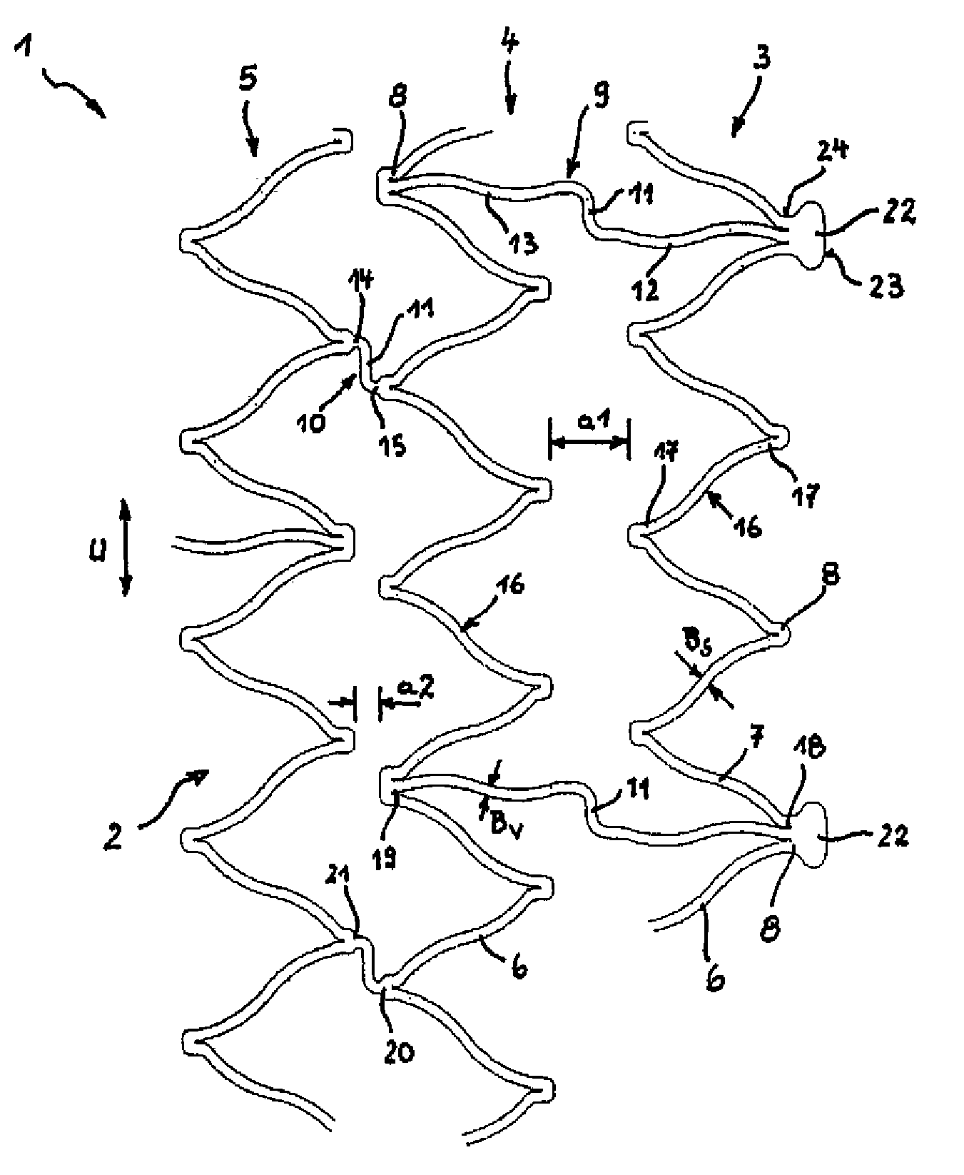
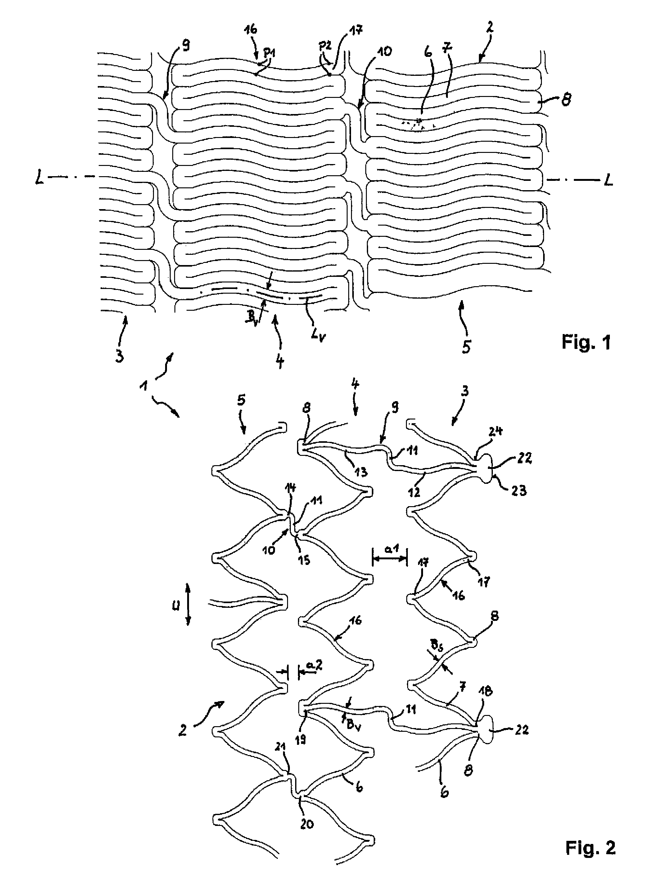
[0036]FIGS. 1 and 2 each show a developed view of a section from the layout pattern of a stent 1 according to the invention. FIG. 1 shows the layout of stent 1 in an unexpanded initial state. FIG. 2 shows the layout of the stent pattern in the expanded supporting state.

[0037]Stent 1 is made of a metal, in particular nitinol, and has a tubular support frame 2 comprised of several sequentially arranged ring segments 3, 4, 5. The stent 1 can generally have different lengths. FIGS. 1 and 2 do not show the total number of a ring segments 3, 4, 5 of the stent 1.

[0038]The ring segments 3, 4, 5 are formed by segment struts 6, 7 which are joined by tie bars 9, 10 in a sequential endless pattern. Depicted are first long tie bars 9 and second short tie bars 10. An arm 11 extending in the circumferential direction U of the support frame 2 is provided in each tie bar 9, 10. The arm 11 is connected on both sides via axial sections 12, 13; 14, 15 to a transition 8. The arms 11 are each arranged in...


PUM


Abstract

Disclosed is a stent (1) representing a prosthesis for a constricted body vessel. The stent (1) includes a tubular support frame (2) composed of ring segments (3, 4, 5) which are sequentially arranged in axial direction and which are formed by segment struts (5, 6) that are continuously joined to one another in the initial state via transitions (8). Adjacent ring segments (3-5) are coupled to each other using tie bars (9, 10). In order to prevent notch stress in the segment struts (5, 6), the width thereof increases from midsection (16) in the direction of the transitions (8), wherein the segment struts (6, 7) are curved in a wave-like manner.

Description

BACKGROUND OF THE INVENTION[0001]The invention relates to a stent.[0002]Stents are used to provide permanent or temporary support of body vessels which are closed or narrowed due to stenosis.[0003]The stents have a tubular support frame made of metal, with the support frame having several ring segments. The ring segments are formed of segment struts which are sequentially arranged in an endless manner and joined by transitions. Adjoining ring segments along the longitudinal axis of the stent are coupled by tie bars.[0004]Stents are available in different constructions and designs of the support frame. WO 96 / 26689, U.S. Pat. No. 5,861,027 A, DE 297 02 671 U1 or DE 295 21 206 U1 are mentioned here as examples.[0005]The stents are inserted using catheter procedures and similar insertion methods into the intravascular region near the stenosis and placed there, whereby the support frame can be widened from the initial state to a supporting state which is increased in diameter. This widen...

Claims


Application Information

Patent Timeline
Patent Type & Authority Patents(United States)
IPC IPC(8): A61F2/06A61F2/00A61F2/91A61F2/915
CPCA61F2/91A61F2/915A61F2002/91516A61F2230/0054A61F2002/91558A61F2002/91566A61F2250/0018A61F2002/91533A61F2/07A61F2/82A61F2/89A61F2/90
Inventor NISSL, THOMAS
Owner QUALIMED INNOVATIVE MEDIZINPROD
Why Eureka
Try Eureka