Spraying robot driving device

A spraying robot and driving device technology, which is applied in the direction of spraying devices, etc., can solve problems such as single form, difficult processing of parts, complex structure of serial spraying robots, etc., and achieve the effect of simple structure, reliable performance, convenient disassembly and maintenance

Inactive Publication Date: 2012-06-27
JIANGSU CHANGHONG INTELLIGENT EQUIP CO LTD
View PDF7 Cites 53 Cited by
  • Summary
  • Abstract
  • Description
  • Claims
  • Application Information

AI Technical Summary

Problems solved by technology

The tandem spraying robot has a complex struc...

Method used


Image

  • Spraying robot driving device
  • Spraying robot driving device
  • Spraying robot driving device

Examples


Embodiment Construction

[0024] The specific embodiments of the present invention will be described in detail below in conjunction with the accompanying drawings.

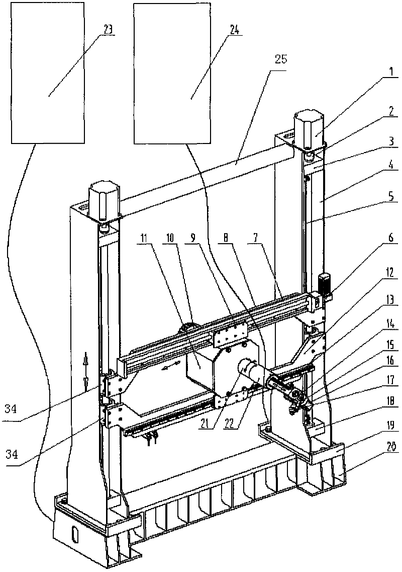
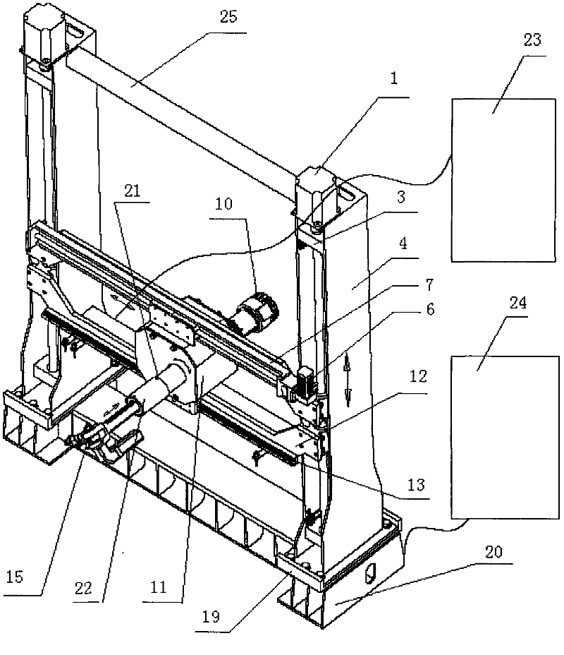
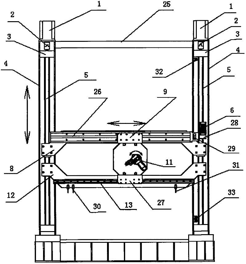
[0025] Figure 1-3 The painting robot of the present invention is shown moving planarly within the frame. Wherein the left and right lifting servo motors 1 are placed on the frame tops of the left and right fuselages 4 . The lower end of the lifting servo motor 1 is connected to the lifting flexible coupling 2, the upper bearing seat 3 and the lifting ball screw 5 in sequence, the upper end of the lifting ball screw 5 is connected to the upper bearing seat 3, and the lower end is connected to the lower bearing seat 18. The left and right fuselages 4 are H-shaped frame structures respectively, and the lifting flexible coupling 2, the upper bearing seat 3, the lifting ball screw 5 and the lower bearing seat 18 are respectively placed in the H-shaped frame of the fuselage 4. Ball nut slider seats 34 at the left and right ends of the upper s...


PUM


Abstract

The invention relates to a robot driving device, comprising a planar intraframe driving device and a mechanical arm driving device, wherein the planar intraframe driving device comprises an up-down lifting driving device and a left-right horizontal driving device. The left-right horizontal driving device drives a spraying robot to horizontally move right and left with a linear module sliding block by virtue of a servo motor, the up-down lifting driving device drives the left-right horizontal driving device to do lifting motion up and down with a ball screw by virtue of the servo motor; the mechanical arm driving device comprises an intermediate rotating driving mechanism, a telescopic driving mechanism and a swinging driving mechanism at the front end, the intermediate rotating driving mechanism drives a mechanical arm to rotate by virtue of the servo motor; the telescopic driving mechanism drives the mechanical arm to do telescopic motion by virtue of the servo motor; and the swinging driving mechanism at the front end drives a spray gun to swing and rotate around by virtue of the servo motor and a reducer.

Description

Technical field: [0001] The invention relates to a spraying robot, in particular to a driving device for a spraying robot Background technique: [0002] The spraying robot used in the existing coating production line is a tandem spraying robot or a reciprocating spraying robot. The reciprocating spraying robot has relatively low flexibility, and the spraying track is single, which wastes paint. [0003] Chinese patent application CN200480008390.1 discloses an example of a spraying robot used in a coating production line, which includes first to fourth robots, which are all controlled by a controller and set close to the transmission line, and an injector mechanism, which is set On the ends of the arms of the first to fourth robots, the actions of which are taught, a liquid comprising acrylic copolymer is sprayed onto the vehicle body. The robot is a multi-joint industrial robot, which includes a base, and a first arm, a second arm, and a third arm in sequence from the base...

Claims


Application Information

Patent Timeline
IPC IPC(8): B05B13/04B05B15/08B05B15/68
Inventor 仇云杰仇云林陈福森张葛林
Owner JIANGSU CHANGHONG INTELLIGENT EQUIP CO LTD
Why Eureka
Try Eureka