Adaptive automatic computer room air conditioners (CRAC) master control method and system

a computer room and master control technology, applied in the field of mechanical cooling system, can solve the problems of sacrificing cooling efficiency and cooling energy consumption, affecting the efficiency of control, so as to minimize cooling energy consumption, and eliminate hot spots.

Active Publication Date: 2017-06-22
ARCHIMEDES CONTROLS CORP
View PDF2 Cites 4 Cited by
  • Summary
  • Abstract
  • Description
  • Claims
  • Application Information

AI Technical Summary

Benefits of technology

[0007]In some embodiments, a logic that uses a special index to determine the thermal health of a data center and for control logic is provided. In some embodiments, this special index is used to control the computer room air conditioning systems. In some embodiments, an algorithm that networks all available HVAC units to help eliminate hot spots is provided. In some embodiments, a generic control logic which can be adapted to any data centers, independent of types of servers, racks, and cooling equipment is provided. In some embodiments, a control logic that minimizes cooling energy consumption and ensures normal operation for data centers is provided. In some embodiments, a fully automatic control logic without human intervention is provided.
[0008]In some embodiments, an adaptive automatic computer room air conditioners (CRAC) master control method for optimizing mechanical cooling systems and minimize cooling energy consumption in data centers comprises determining a rack cooling index over temperature (RCIHI) for one or more racks under control of a first CRAC, determining the existence of hot spots using the determined RCIHI, maintaining the RCIHI at a desired level by generating cooling requests to one or more other CRACs in addition to the first CRAC when hot spots occur or persist, and recalling the cooling requests when the hotspot is eliminated.

Problems solved by technology

To ensure safe operation of a data center, its cooling system usually is over sized and runs excessively to keep it as cool as possible.
This however sacrifices cooling efficiency and cooling energy consumption therefore skyrockets.
Some of them adapt several inherently conflicting indices in their control logic, resulting in less efficient control results.
Some use a single HVAC unit to address hot spots, resulting in unsatisfactory thermal conditions.
Still some require human intervention and are not automatic enough.

Method used


Image

  • Adaptive automatic computer room air conditioners (CRAC) master control method and system
  • Adaptive automatic computer room air conditioners (CRAC) master control method and system
  • Adaptive automatic computer room air conditioners (CRAC) master control method and system

Examples


Embodiment Construction

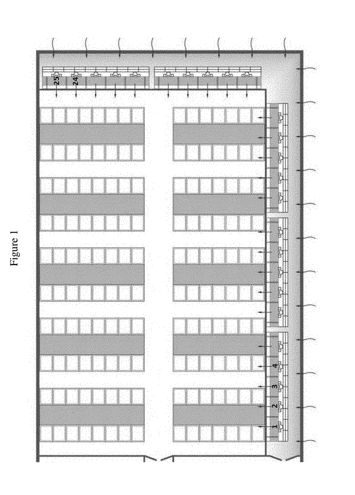
[0014]FIG. 1 is a plan view of a data center 1. The data center 1 includes one or multiple racks (rack 2) and CRAC units (CRAC unit 3). A rack 2 consists of one or multiple computer equipment. For example, there are 25 CRACs and 10 columns of racks, with 15 racks each column in FIG. 1. This method can be used in rooms with any numbers of CRAC units.

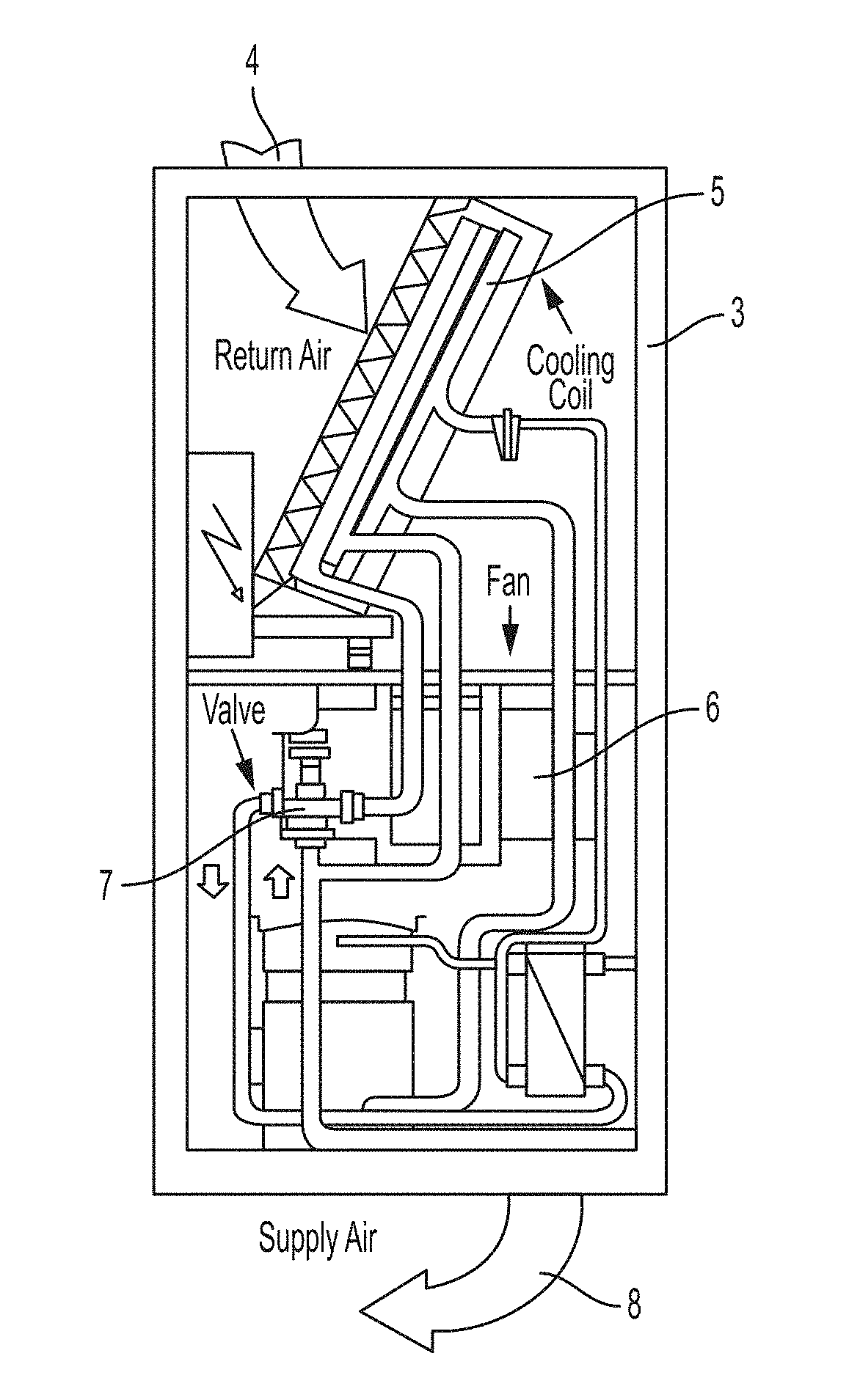
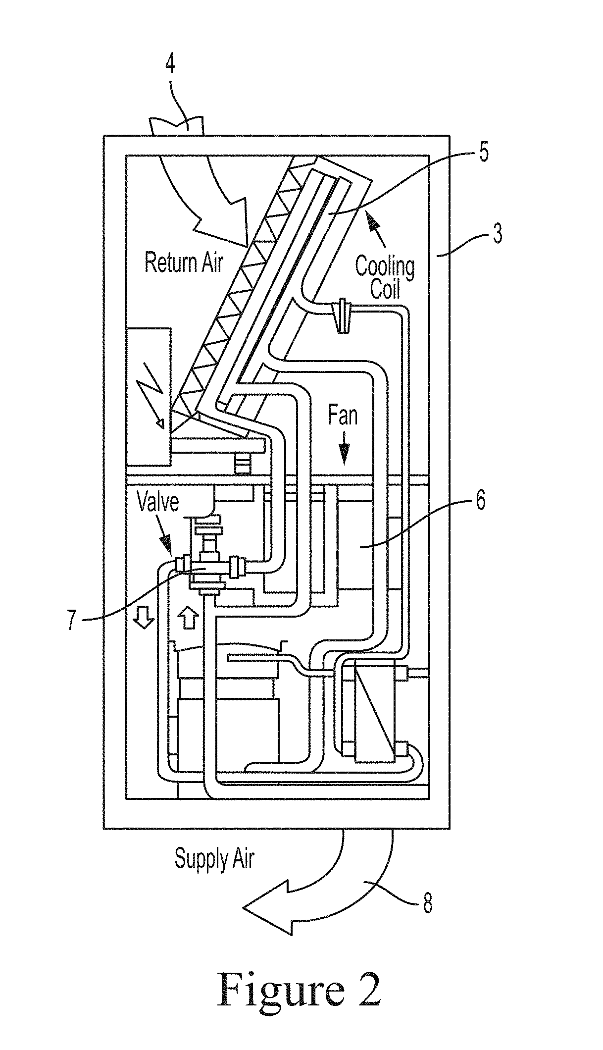
[0015]FIG. 2 is an elevation view of a CRAC unit 3 shown in FIG. 1. Return air 4 from internal space of the data center 1 is drawn by the supply fan 6 through the top of the unit. After passing through the cooling coil 5, it is cooled and becomes cool supply air 8. Inside the cooling coil 5 runs chilled water, refrigerant or other cold media, the flow of which is regulated by the cooling valve 7. Temperature of the return air 4 (RAT) usually is the control target of the CRAC unit 3. Speed of the supply fan 6 or the cooling valve 7 or another means is adjusted to vary the cooling output of the CRAC unit 3 and maintain the control target, i...


PUM


Abstract

Described is an adaptive automatic computer room air conditioner (CRAC) or computer room air handler (CRAH, CRAC and CRAH is referred interchangeably in this article) group control method. This method automatically controls each HVAC unit's on/off status, return temperature set point, fan speed or cooling valve position to secure the data center thermal environment for server's secure running and minimize the cooling energy use. The method creates a comprehensive feedback control loop between temperature sensor network, data center environment and CRACs.

Description

CROSS-REFERENCE TO RELATED APPLICATION[0001]This application claims the benefit of U.S. Provisional Application No. 62 / 269,913, filed Dec. 18, 2015, the entire contents of which is incorporated herein by reference.FIELD OF THE INVENTION[0002]The present invention relates to mechanical cooling system optimal control and energy efficiency.BACKGROUND OF THE INVENTION[0003]Data centers are one of the largest and fastest growing consumers of electricity in the United States. In 2013, U.S. data centers consumed an estimated 91 billion kilowatt-hours of electricity—enough electricity to power all the households in New York City twice over—and are on-track to reach 140 billion kilowatt-hours by 2020. To ensure safe operation of a data center, its cooling system usually is over sized and runs excessively to keep it as cool as possible. This however sacrifices cooling efficiency and cooling energy consumption therefore skyrockets. A smart cooling system control logic which drives the cooling ...

Claims


Application Information

Patent Timeline
Patent Type & Authority Applications(United States)
IPC IPC(8): F24F11/00H05K7/20G05B15/02
CPCF24F11/0012G05B15/02F24F11/0086F24F11/006G05B2219/2614H05K7/20745F24F2011/0047F24F2011/0091F24F2011/0061H05K7/20836F24F11/62F24F11/30F24F11/47F24F11/46F24F11/63F24F11/84F24F11/77F24F2140/60F24F11/52G05B13/024F24F2110/10
Inventor LIU, XIANGTAN, LIANGCAIHU, XIN
Owner ARCHIMEDES CONTROLS CORP
Why Eureka
Try Eureka