Method and apparatus for providing a simulated neon sign

a neon sign and neon light technology, applied in the field of lighting devices, can solve the problems of fragile neon light signs, achieve the effects of improving light scattering characteristics, adequate strength, and eliminating hot spots

Inactive Publication Date: 2012-06-28
KAOH ANDY K F
View PDF7 Cites 10 Cited by
  • Summary
  • Abstract
  • Description
  • Claims
  • Application Information

AI Technical Summary

Benefits of technology

[0013]Alternatively, light transmission spherical particles of a different index of refraction from that of the light transmissive curved plastic resin can also be used to improve light scattering characteristics. For example, a polymer based diffusion compound formulated for an acrylic clear plastic can also be used to eliminate the hot spots that could be caused, for example, by an LED in an application such as signage. Spherical polymer particles can scatter and spread light to provide an even illumination while allowing light transmission levels of 90% or more.
[0014]Preferably the physical size of support connections, for structural purposes between the outer housing and the inner housing, are minimized while providing adequate strength, thereby optimizing the appearance of a conventional neon tube sign. Such connections can be rectangular, tubular hollow members that can be molded.
[0015]To minimize the components that must be assembled to create the lighting apparatus for simulating a neon sign, an upper member housing that forms the inverted U-shape can be molded in a two part procedure wherein initially the side legs of the upper member and flat upper surfaces of connection portions are molded from an acrylonitrile-butadiene-styrene (ABS) co-polymer which is a thermal setting resin that can provide an opaque or black appearance. Subsequently, a light transmissive curved upper surface can also be integrally molded with an appropriate light scattering filler material that can be combined with the opaque side walls. A clear polymethyl methacrylate with appropriate filler material can be utilized to permit the curved portion of the U-shaped upper housing to simulate a neon tube while obscuring any hot spots or appearance of the light source.

Problems solved by technology

Neon light signs, however, are fragile and are usually shaped by an artisan by applying heat to lead glass tubing to provide a desired shape.

Method used


Image

  • Method and apparatus for providing a simulated neon sign
  • Method and apparatus for providing a simulated neon sign
  • Method and apparatus for providing a simulated neon sign

Examples


first embodiment

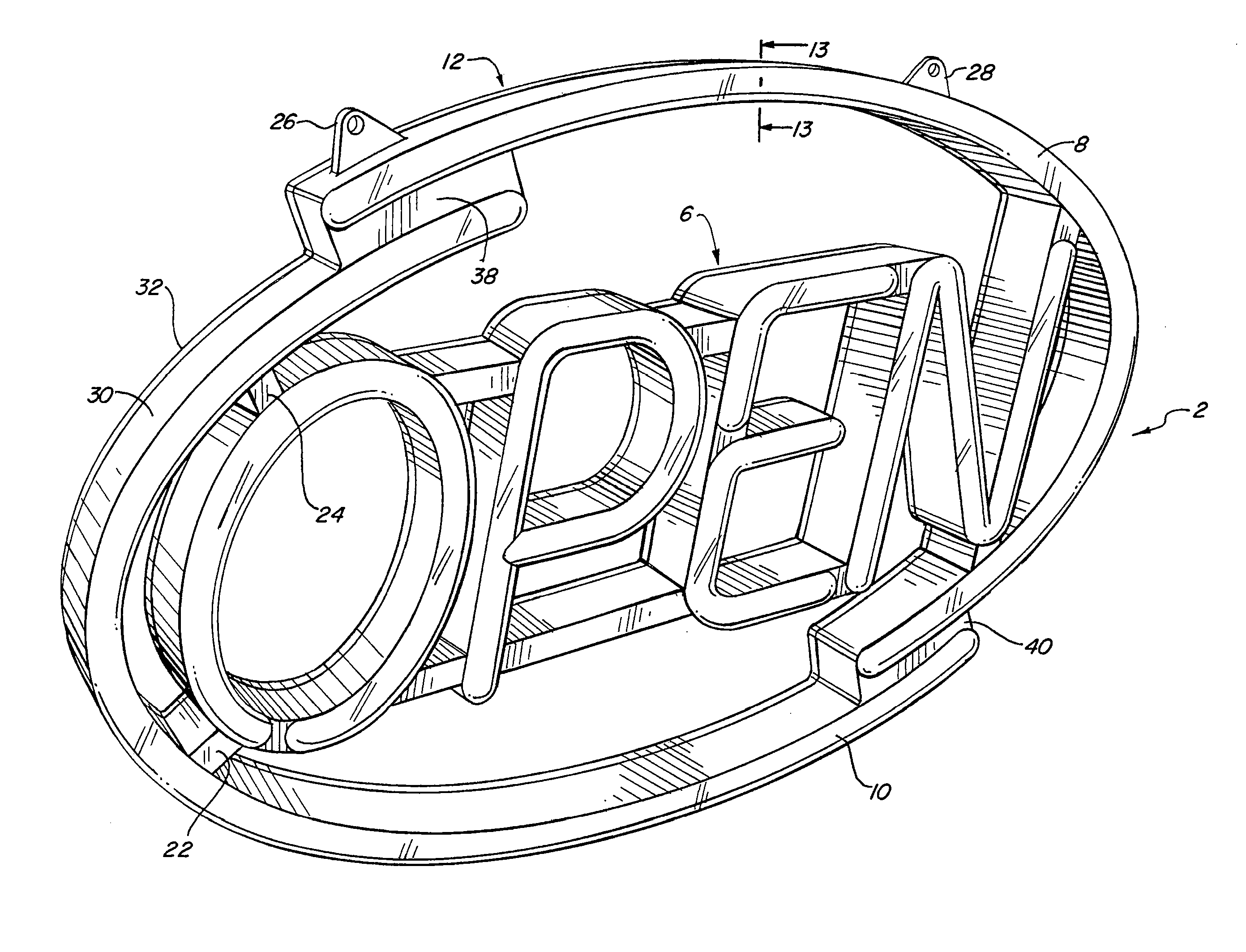
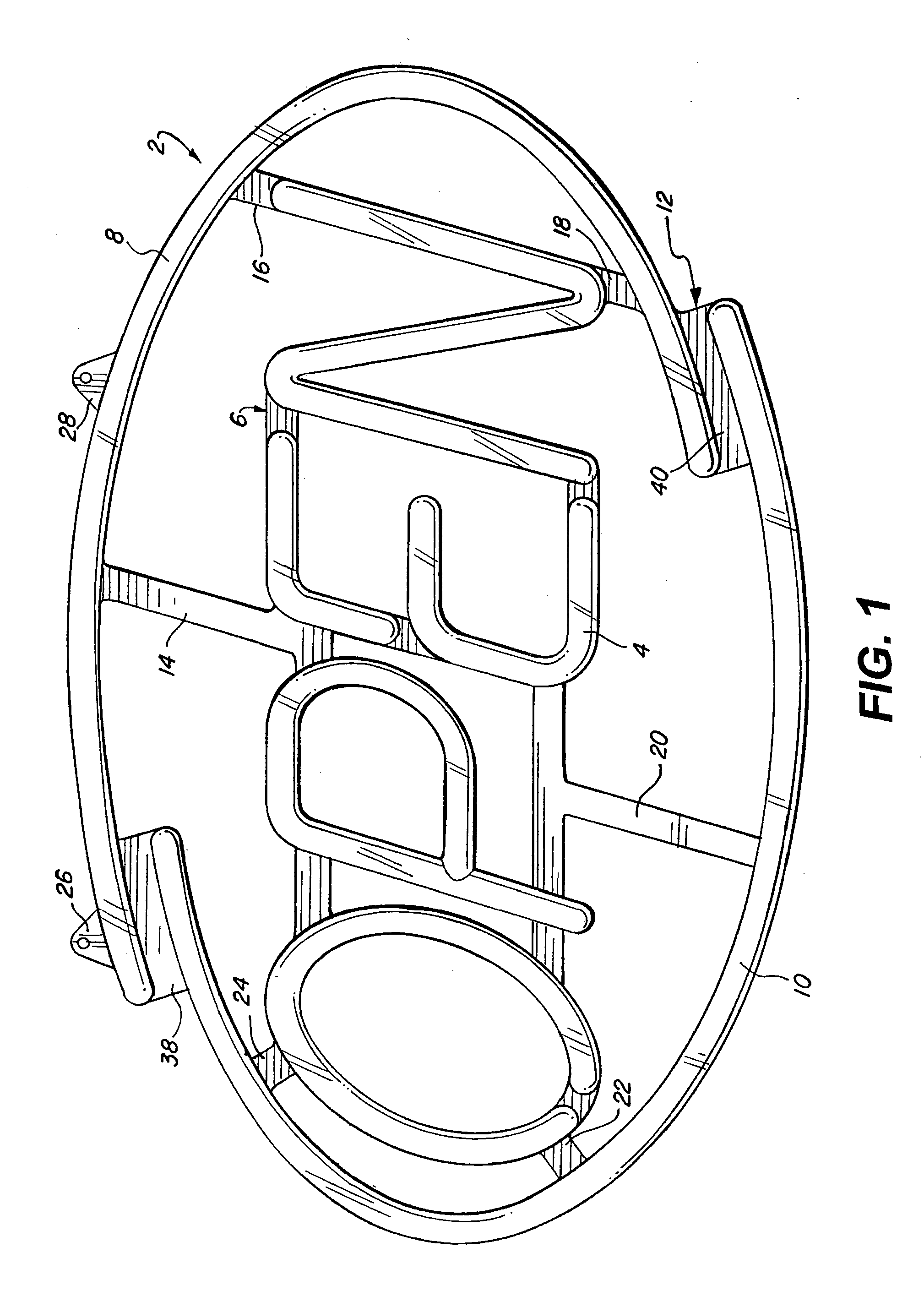
[0038]Referring to FIG. 1, the present invention is disclosed in a lighting assembly 2 capable of simulating a neon sign. Symbols are arranged as indicia to convey a message. In this regard, alphabetic characters are defined by light transmissive areas simulating neon tubes to spell OPEN. Accentuating the sign message are a pair of open curved members of a light transmissive nature to also simulate neon tubes. The symbols of letters 4 are mounted on an inner housing 6.

[0039]Encircling the inner housing 6 are a pair of curved light transmissive portions 8 and 10 on an outer housing 12 that forms a perimeter around the inner housing 6. Support members 14, 16, 18, 20, 22, and 24 having a hollow rectangular cross-sectional configuration interconnect the inner housing 6 with the outer housing 12. The support members are preferably molded and formed from an opaque or black resin material that approximate the thickness of the symbols 4 and the respective curved light transmissive portions ...

third embodiment

[0043]FIGS. 8-12 disclose a third embodiment and common elements that are utilized in the drawings for FIG. 1 are repeated in these views.

[0044]The major difference is that the signage is only supported at either end, within the central opening of the outer housing 12 to support members 16 and 18 and elongated support member 68.

[0045]As can be appreciated, in the third embodiment, the elongated support member 68 adjacent the O letter could be replaced with the smaller support members 24 and 22 shown in FIG. 7.

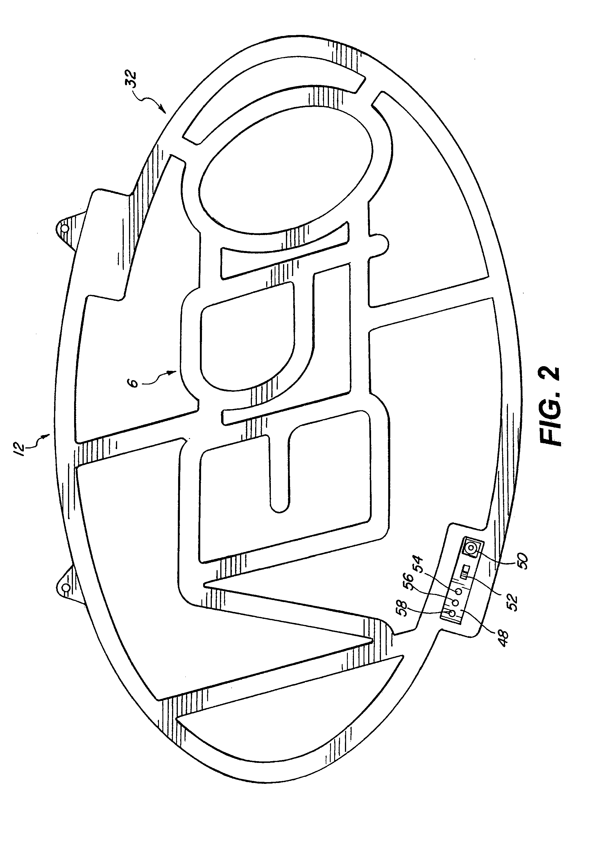
[0046]As seen in FIG. 11, a plurality of open slots 70 can be provided in the base member 32 to provide ventilation for the release of heat generated by the LED's.

[0047]Referring to FIG. 12, the base member 32 represents basically a minor image of the back side of upper member 30 so that the cavity openings, that receive the elongated strips of printed circuit board substrates supporting the individual SMD LED 60, are isolated to prevent any light pollution between the individu...


PUM

PropertyMeasurementUnit
voltageaaaaaaaaaa
particle sizeaaaaaaaaaa
diameteraaaaaaaaaa

Abstract

A lighting apparatus for simulating a neon sign and method of making is provided. An outer housing having a central opening and defining a perimeter of the lighting apparatus can be connected with an inner housing configured as a plurality of symbols for conveying a message. Mounted within the interior of the outer and inner housing can be a series of lighting units such as SMD light emitting diodes. Respective outer housing and inner housing can have a cross-sectional inverted U-shape capped by a base member with the upper member having a curved diffuser for transmitting light through a transmissive plastic resin while integrally mounted black or opaque straight legs of a U-shape can enhance the simulated neon glow.

Description

CROSS-REFERENCE TO RELATED APPLICATION[0001]This is a continuation in part application of U.S. Design patent application Ser. No. 29 / 332,476 filed Feb. 17, 2009.BACKGROUND OF THE INVENTION[0002]1. Field of the Invention[0003]The present invention relates to a lighting device and more particularly, signage devices that can simulate the appearance of a neon gas sign without the cost or possibility of breakage of a conventional neon gas sign.[0004]2. Description of Related Art[0005]Conventional establishments such as retail outlets, restaurants and convenience stores have made extensive use of neon light signs to convey a commercial message and the appearance of such neon light signs have become acceptable to customers. Bright, uniform and colorful light distribution emanated from a neon light medium will attract attention and can be subjectively configured to provide an attractive advertising medium. Neon light signs, however, are fragile and are usually shaped by an artisan by applyi...

Claims


Application Information

Patent Timeline
Patent Type & Authority Applications(United States)
IPC IPC(8): G09F13/04B29C31/08
CPCG09F13/22
Inventor KAOH, ANDY K. F.
Owner KAOH ANDY K F
Why Eureka
Try Eureka