Multi-forming device

Active Publication Date: 2017-06-29
SUNG WOO HITECH
View PDF3 Cites 0 Cited by
  • Summary
  • Abstract
  • Description
  • Claims
  • Application Information

AI Technical Summary

Benefits of technology

[0026]Particularly, while a product is deformed to a final shape through blow forming at a super-plasticity temperature of an aluminum alloy, a swirl is formed within a shaping gas that has passed a gap of a deformed material through a gas passage, and thus a high temperature shaping gas does not leak and uniformly flows therein to improve blow formability, in a condition that an inner gas pipe is disposed in a gas passage of a lower mold to be opened/closed by a switch valve and an initial

Problems solved by technology

However, the magnesium has high specific strength, and it can be light in weight at 30% lighter than an aluminum alloy, but it is disadvantageous in an aspect of cost, corrosion, formability, and welding characteristics compared to other materials such as an aluminum alloy.
Particularly, in a case that a product having a complicated shape or a product having a large deformation depth is produced, there are drawbacks that the number of processes and the number of components are increased due to limitations of formability, forming cost is increased, and productivity is d

Method used


Image

  • Multi-forming device
  • Multi-forming device
  • Multi-forming device

Examples


Example

[0031]Hereinafter, an exemplary embodiment of the present invention will be described with reference to accompanying drawings.

[0032]Further, the sizes and thicknesses of the configurations shown in the drawings are selectively provided for convenience of description, and the present invention is not limited to those shown in the drawings, and to clearly describe the present invention, parts that are irrelevant to the description will be omitted.

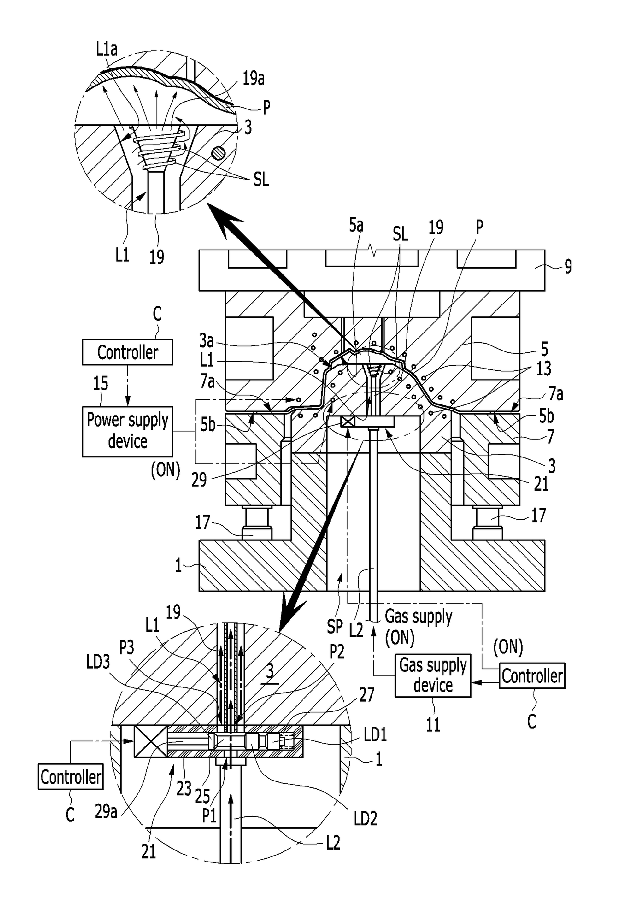
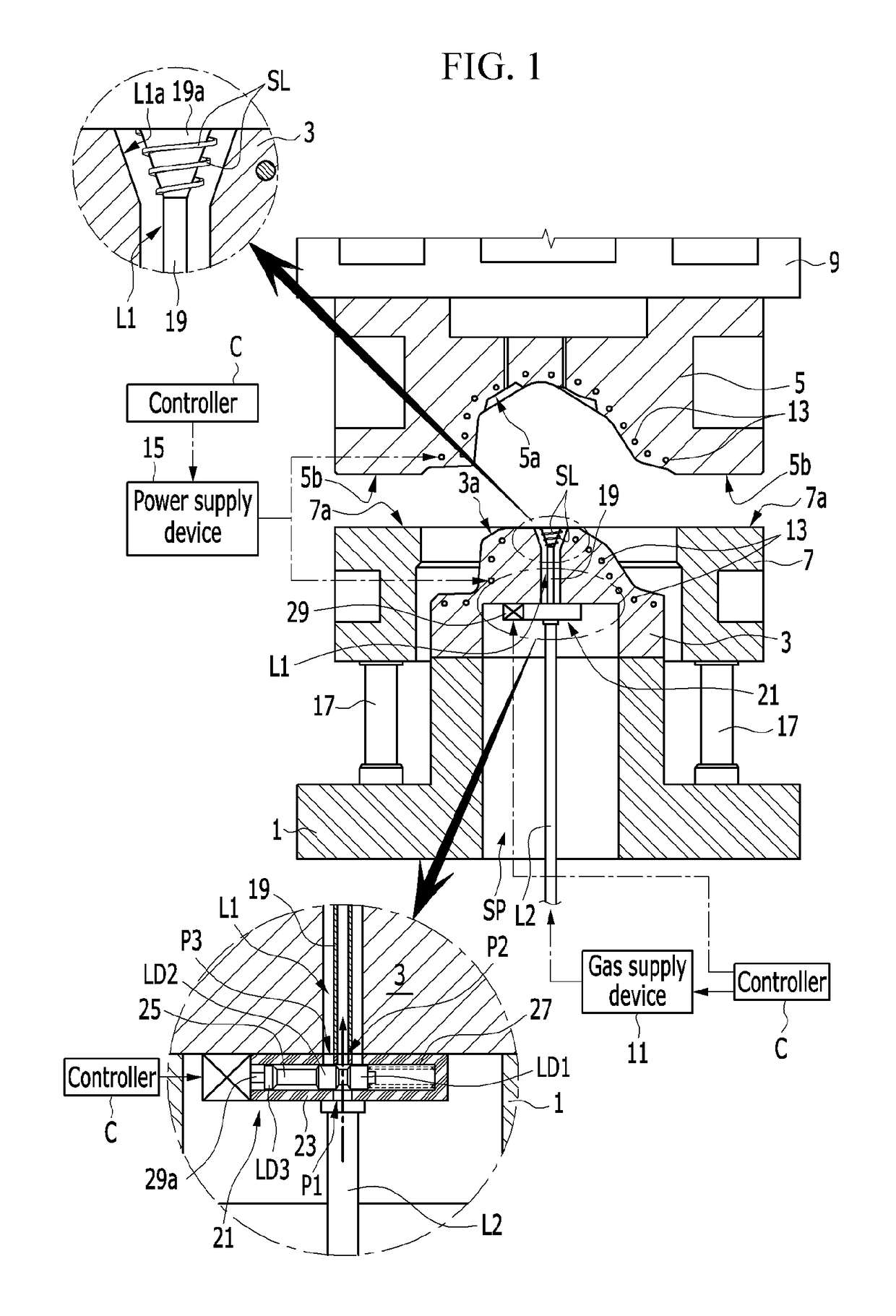
[0033]FIG. 1 is a sectional schematic diagram of a multi-forming device according to an exemplary embodiment of the present invention.

[0034]Referring to FIG. 1, in a multi-forming device according to an exemplary embodiment of the present invention, after an aluminum alloy plate as a super-plasticity material is shaped by warm-forming to a maximum deformation depth, while it is being shaped to a final product by blow-forming, an initial shaping pressure of a material is formed by a switch valve that is disposed on an inner gas pipe that is di...


PUM

PropertyMeasurementUnit
Diameteraaaaaaaaaa
Densityaaaaaaaaaa
Shapeaaaaaaaaaa

Abstract

A multi-forming device is disclosed. A multi-forming device according to an exemplary embodiment of the present invention may include: a lower mold die; a lower mold that is disposed at a center upper surface of the lower mold die, in which a gas passage is formed in an up-and-down direction to receive a shaping gas from an outside gas supplier device, in which a lower mold surface is formed at an upper surface thereof, and in which a plurality of heating cartridges are disposed therein along the lower surface thereof; an upper mold that is disposed on an upper side slider to be moved in an up-and-down direction corresponding to the lower mold, in which an upper mold surface is formed at a lower surface corresponding to the lower mold, in which an upper mold face is formed at a circumference of the upper mold surface, and in which a plurality of heating cartridges are disposed along the upper mold surface; a blank holder through which the lower mold is inserted and that is disposed to move in an up-and-down direction through a cushion spring on the lower mold die, and in which a holder face is formed to grasp a material together with the upper mold face at an early stage of a forming process; an inner gas pipe that is disposed in a gas passage of the lower mold; and a switch valve that switches supply passages of the shaping gas that is supplied to the inner gas pipe and the gas passage.

Description

CROSS-REFERENCE TO RELATED APPLICATION[0001]This application claims priority to and the benefit of Korean Patent Application No. 10-2015-0188970 filed in the Korean Intellectual Property Office on Dec. 29, 2015, the entire contents of which are incorporated herein by reference.BACKGROUND OF THE INVENTION[0002](a) Field of the Invention[0003]The present invention relates to a multi-forming device. More particularly, the present invention relates to a multi-forming device that uses one mold to perform warm forming and blow forming and produces a product having a deep deformation depth and a complicated shape through one process.[0004](b) Description of the Related Art[0005]Generally, a warm forming process has been developed to press a magnesium alloy sheet of a lightweight material of which a density of the metal structure is lower than that of an aluminum alloy sheet, and has recently been under development and is being applied by demand of various press forming methods so as to app...

Claims


Application Information

Patent Timeline
IPC IPC(8): B21D26/027B21D26/055B21D26/031
CPCB21D26/027B21D26/055B21D26/031
Inventor PARK, SANGHYUNKIM, RAE HYEONGLEE, MUN YONG
Owner SUNG WOO HITECH
Why Eureka
Try Eureka