Fluid restriction nozzle for hand washing

a technology of limiting nozzles and nozzles, which is applied in the direction of spray nozzles, water installations, construction, etc., can solve the problems of not providing a sufficient reduction of fluid flow, and achieve the effects of reducing water consumption, reducing water flow rate, and reducing fluid flow

Active Publication Date: 2017-06-29
BAMFORD NIGEL
View PDF9 Cites 3 Cited by
  • Summary
  • Abstract
  • Description
  • Claims
  • Application Information

AI Technical Summary

Benefits of technology

[0002]It is desirable to reduce water consumption in both the home and commercial premises. One way of doing so is to reduce the water flow rate from taps, such as those used in kitchens and bathrooms. It is known to use nozzles on taps in order to reduce the flow of fluid therethrough. Commonly used nozzles include aerating nozzles. However, such nozzles may not provide a sufficient reduction in fluid flow. Therefore, there remains a need for reducing the flow of fluid from a tap further, while still providing a flow that is capable of cleaning a user's hands.

Problems solved by technology

However, such nozzles may not provide a sufficient reduction in fluid flow.

Method used


Image

  • Fluid restriction nozzle for hand washing
  • Fluid restriction nozzle for hand washing
  • Fluid restriction nozzle for hand washing

Examples


Embodiment Construction

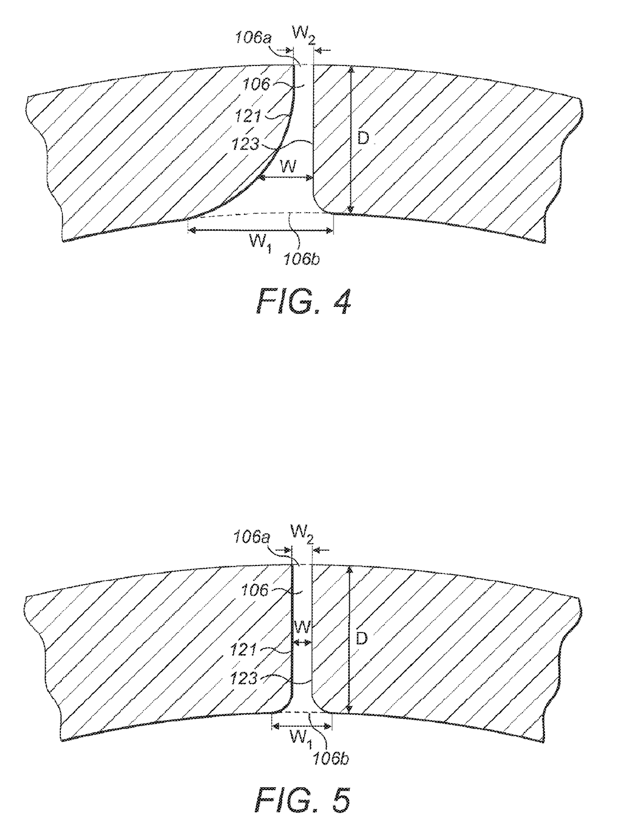
[0089]In the below described embodiments, the interior and exterior elongated apertures of the flow restriction nozzle are formed on a hemispherical surface. However, it should be understood that the apertures can be formed on any tapered surface, such as the edge of a cylinder, provided that the aperture extends over the tapered surface, i.e. along the direction of curvature / tapering.

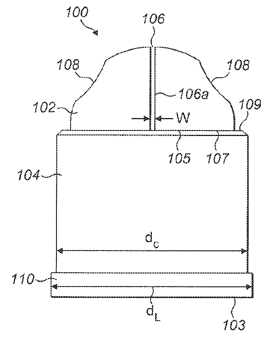
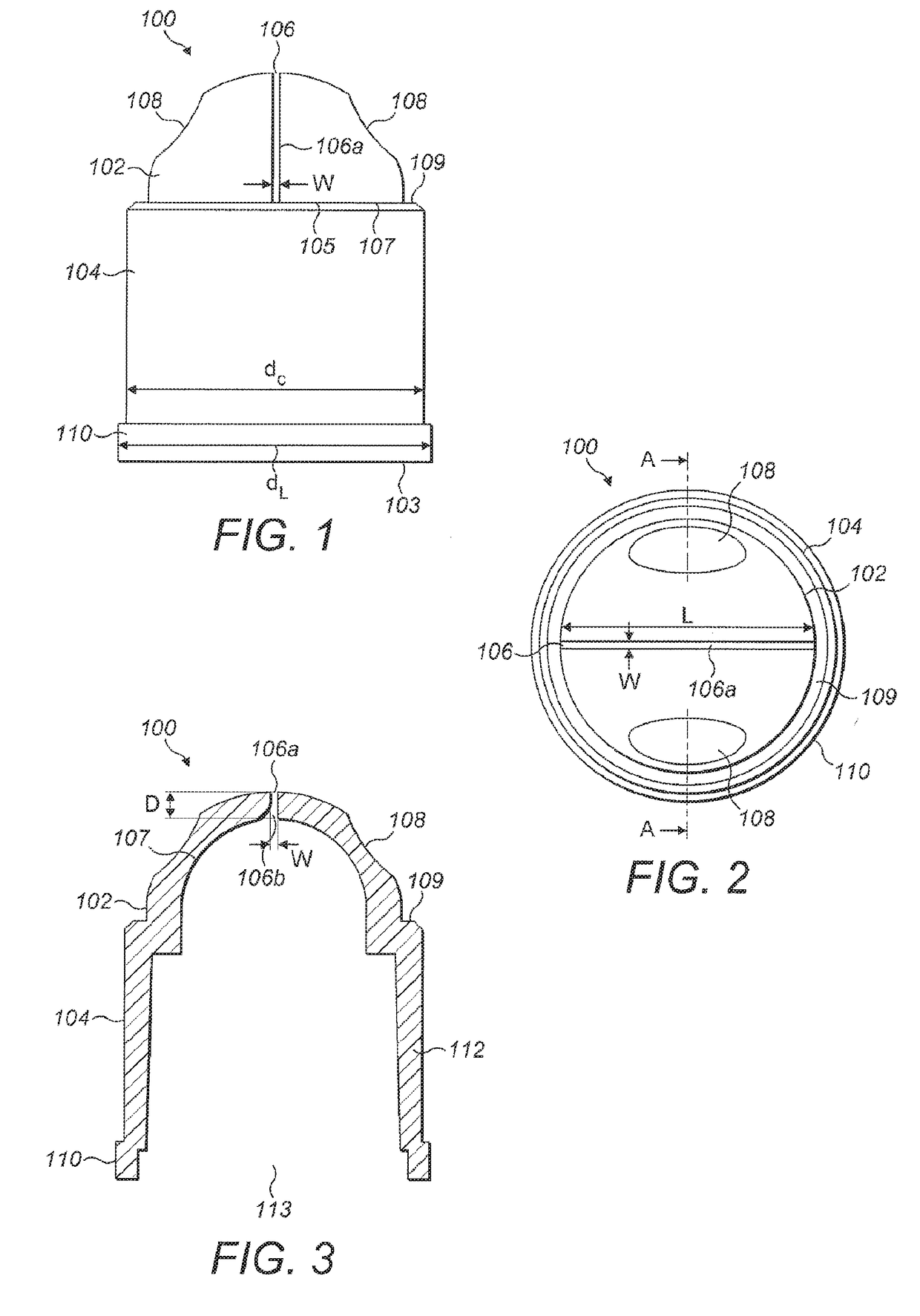
[0090]FIGS. 1 to 3 show a flow restriction nozzle 100 having a single aperture 106. The nozzle 100 comprises a cylindrical portion 104 and a hemispherical portion 102. The nozzle 100 is hollow and is formed from injection moulded plastic. The walls 112 of the nozzle 100 are approximately 1 mm thick (in non-thinned regions). The cylindrical portion 104 and hemispherical portion 102 are arranged such that the circular end 107 of the hemispherical portion 102 abuts the distal circular end 105 of the cylindrical portion 04. Due to the differing radii, an optional flange 09 extends therebetween. The cylindr...


PUM


Abstract

A flow restriction nozzle (100) comprising an interior surface, an exterior surface, an inlet (103) at a first portion of the nozzle (100) for connection to a fluid source, and an outlet (106) at a second portion of the nozzle (100) for providing a fluid flow, connecting the interior surface to the exterior surface, wherein a portion of the interior surface tapers radially inwardly towards the second portion and the outlet (106) comprises an elongated aperture (106) formed in the interior surface extending at least partially along the tapered surface such that a portion of the fluid flow through the outlet (106) is directed radially outwardly.

Description

BACKGROUND OF THE INVENTION[0001]The present invention relates to a fluid flow restriction nozzle and, in particular, a nozzle for use with a tap for hand washing.SUMMARY OF THE INVENTION[0002]It is desirable to reduce water consumption in both the home and commercial premises. One way of doing so is to reduce the water flow rate from taps, such as those used in kitchens and bathrooms. It is known to use nozzles on taps in order to reduce the flow of fluid therethrough. Commonly used nozzles include aerating nozzles. However, such nozzles may not provide a sufficient reduction in fluid flow. Therefore, there remains a need for reducing the flow of fluid from a tap further, while still providing a flow that is capable of cleaning a user's hands.[0003]The present invention seeks to solve the problems associated with the prior art nozzles.[0004]One aspect of the present invention provides a flow restriction nozzle comprising an interior surface, an exterior surface, an inlet, at a firs...

Claims


Application Information

Patent Timeline
Patent Type & Authority Applications(United States)
IPC IPC(8): E03C1/086E03C1/02B05B1/04E03C1/08
CPCE03C1/086B05B1/04E03C1/02E03C1/08B05B1/046E03C2001/026B05B1/30
Inventor BAMFORD, NIGEL
Owner BAMFORD NIGEL
Why Eureka
Try Eureka