Collision risk calculation device, collision risk display device, and vehicle body control device

a technology of collision risk and display device, which is applied in the direction of control device, external condition input parameter, instruments, etc., can solve the problems of unnecessary actions and inability to accurately estimate the collision risk

Active Publication Date: 2017-06-29
MITSUBISHI ELECTRIC CORP
View PDF2 Cites 25 Cited by
  • Summary
  • Abstract
  • Description
  • Claims
  • Application Information

AI Technical Summary

Benefits of technology

[0012]The collision risk calculation device, collision risk display device, and vehicle body control device of the present invention change a range of a risk map in left and right directions with respect to a traveling direction of an obstacle on the basis of the speed of the obstacle, and thus can reflect, in the risk map, the possibility of a right or left turn of the obstacle, which varies depending on the speed of the obstacle.

Problems solved by technology

However, when the range of the risk map is uniformly determined depending on the relative speed, the risk of collision cannot be accurately estimated.
As such, the collision risk calculation device described in Patent Literature 1 uniformly sets the range of the risk map to be large in left and right directions depending on the relative speed of the own vehicle relative to the speed of the front obstacle even when the speed of the front vehicle is significantly high, and thus may cause unnecessary actions, such as an action of largely avoiding an obstacle to the own vehicle or sudden braking.

Method used


Image

  • Collision risk calculation device, collision risk display device, and vehicle body control device
  • Collision risk calculation device, collision risk display device, and vehicle body control device
  • Collision risk calculation device, collision risk display device, and vehicle body control device

Examples


first embodiment

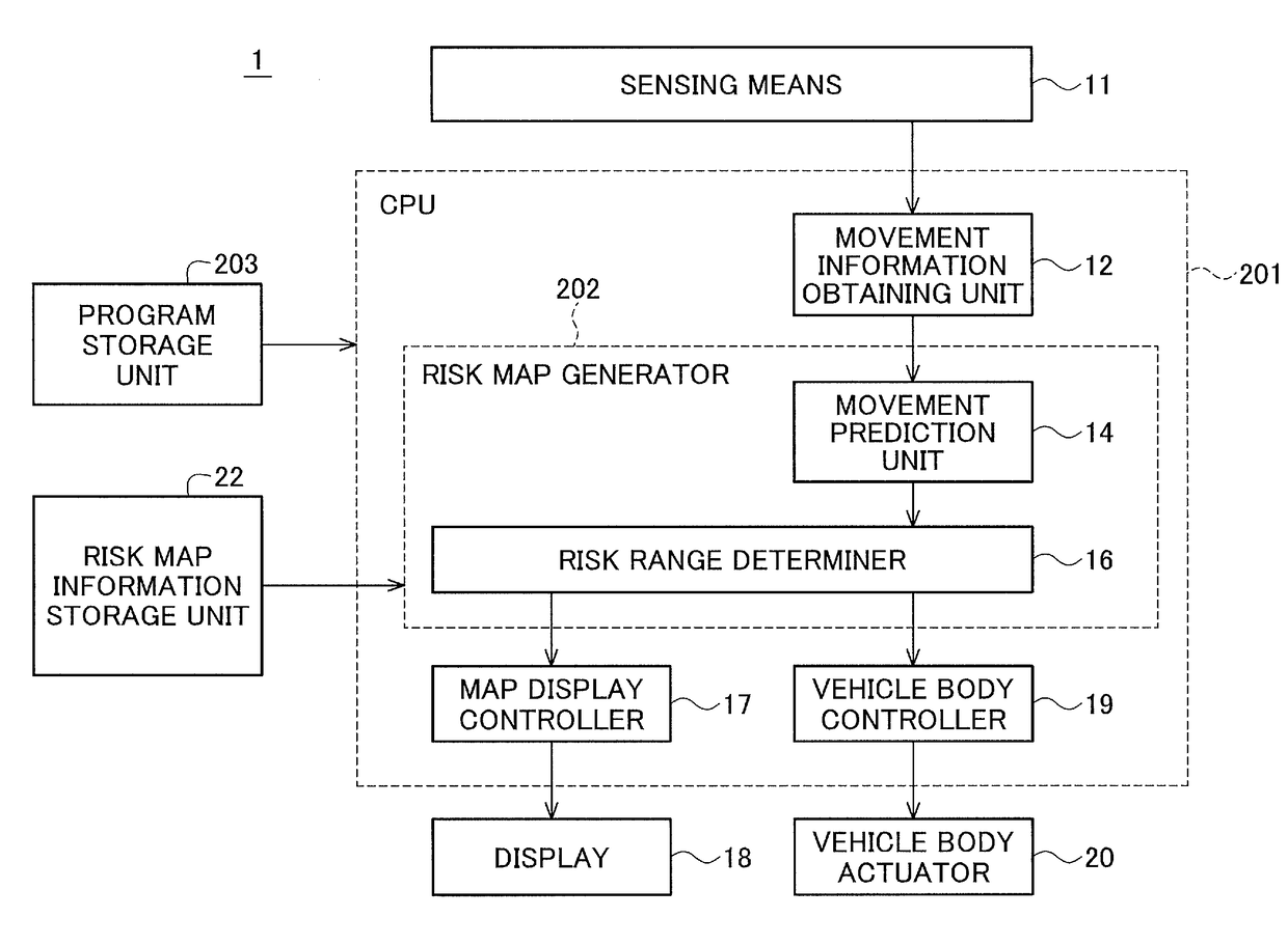
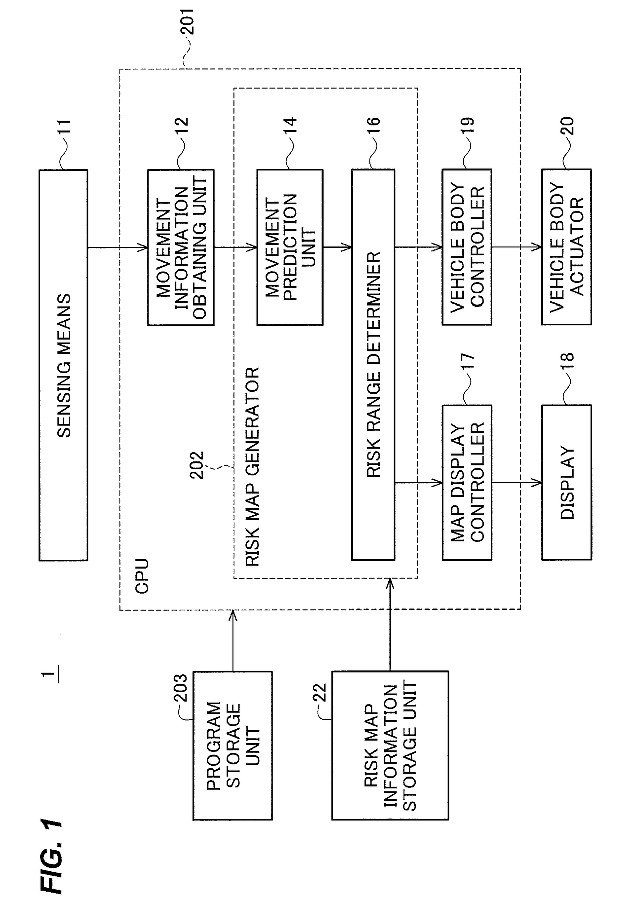
[0038]A vehicle body control device 1 according to a first embodiment will be described below with reference to FIG. 1. FIG. 1 is a configuration diagram of the vehicle body control device 1 according to the first embodiment.

[0039]The vehicle body control device 1 detects an obstacle, generates a risk map of the obstacle, and controls a traveling direction of an own vehicle on the basis of the risk map. The vehicle body control device 1 includes a sensing means (or sensor) 11, a central processing unit (CPU) 201, a program storage unit 203, a risk map information storage unit 22, a display (or display unit) 18, and a vehicle body actuator 20. The CPU 201 includes a movement information obtaining unit 12, a risk map generator 202, a map display controller 17, and a vehicle body controller 19. The risk map generator 202 includes a movement prediction unit 14 and a risk range determiner 16. In the following description, a device including the movement information obtaining unit 12 and ...

second embodiment

[0066]A vehicle body control device of a second embodiment will be described below. The vehicle body control device according to the second embodiment is characterized in that it takes into account the possibility of a right or left turn of an obstacle, and changes the degree of risk of the risk map depending on the type of the obstacle.

[0067]A configuration of the vehicle body control device according to the second embodiment will be described below with reference to FIG. 10. FIG. 10 is a configuration diagram of the vehicle body control device according to the second embodiment. In this embodiment, the sensing means 11 includes a means, such as a camera, capable of imaging an obstacle. In the description of FIG. 10, elements that are the same as those illustrated in FIG. 1 will be given the same reference numerals and descriptions thereof will be omitted.

[0068]The vehicle body control device 1 according to the second embodiment includes an obstacle determiner 21 that determines th...

third embodiment

[0073]A vehicle body control device of a third embodiment will be described below. The vehicle body control device according to the third embodiment is characterized in that it takes into account the possibility of a right or left turn of an obstacle, and changes the range of a risk map depending on a condition of a road surface.

[0074]A configuration of the vehicle body control device according to the third embodiment will be described below with reference to FIG. 12. FIG. 12 is a configuration diagram of the vehicle body control device according to the third embodiment. In this embodiment, the sensing means 11 includes a means for sensing information regarding a road surface condition. In the description of FIG. 12, elements that are the same as those illustrated in FIGS. 1 and 10 will be given the same reference numerals and descriptions thereof will be omitted.

[0075]The vehicle body control device according to the third embodiment includes a road surface condition determiner 23 t...


PUM


Abstract

A collision risk calculation device includes: a movement information obtaining unit that obtains a speed and a movement direction of an obstacle; and a risk map generator that generates a risk map indicating a range within which the obstacle can exist after one unit of time and degree of risk of collision of an own vehicle with the obstacle within the range, on a basis of the speed and the movement direction of the obstacle obtained by the movement information obtaining unit, wherein the risk map generator changes the range in left and right directions with respect to a traveling direction of the obstacle, on a basis of the speed of the obstacle in the traveling direction.

Description

TECHNICAL FIELD[0001]The present invention relates to a collision risk calculation device that calculates risk of collision of a vehicle with an obstacle, a collision risk display device that displays the obtained collision risk, and a vehicle body control device that controls the vehicle on the basis of the collision risk.BACKGROUND ART[0002]Until now, driver assistance techniques have been intended to provide assistance, such as warning deviation from a lane or keeping the speed of a vehicle constant, to drivers. However, in recent years, with increase in awareness of safety, and advancement in performance and price reduction of processors or various sensor devices, driver assistance techniques relating to active safety, such as emergency automatic braking or emergency steering avoidance, for avoiding collision with obstacles have been commercialized, researched, and developed. In driver assistance techniques for avoiding collision with obstacles, it is necessary to properly perce...

Claims


Application Information

Patent Timeline
Patent Type & Authority Applications(United States)
IPC IPC(8): G08G1/16
CPCG08G1/16G08G1/166G08G1/167B60W30/0956B60W2554/804B60W2554/80B60W2554/801B60W2554/00B60W2554/4044B60W30/09B60W2554/4026B60W2554/4029
Inventor TSUSHIMA, NAOYUKIABUKAWA, MASAHIRO
Owner MITSUBISHI ELECTRIC CORP
Why Eureka
Try Eureka