
Method and apparatus for shifting control areas in a wireless communication system

a wireless communication system and control area technology, applied in the direction of site diversity, location information based service, diversity/multi-antenna system, etc., can solve the problems of limited computational resources available for scheduling in any given control area, increased backhaul requirements, and low level of service, so as to improve the performance of wireless communication

Active Publication Date: 2017-06-29
HUAWEI TECH CO LTD
View PDF2 Cites 2 Cited by
  • Summary
  • Abstract
  • Description
  • Claims
  • Application Information

AI Technical Summary

Benefits of technology

The present invention provides methods and apparatus to improve wireless communications by assigning access nodes to control areas for a period of time and reassigning access nodes to control areas during subsequent periods of time. This helps in forming clusters of access nodes appropriate for CoMP scheduling and avoids having access nodes remaining at control area boundaries where they would suffer from reduced performance due to edge affects. Overall, this helps improve the performance of wireless communications.

Problems solved by technology

With this conventional approach, a user node at the edges of a cell may suffer from weak signals and inter-cell interference (ICI) resulting in a lower level of service.
However, this higher performance comes at the cost of increased backhaul requirements.
Forming groups of CoMP clusters in large wireless network environments presents a number of problems.
Computational resources available for scheduling in any given area being controlled are limited, so the size of the area controlled, or the control area, will also be limited.
When the control area is small, such as a single cluster of access nodes, extensive interference can be introduced from adjacent control areas.
There is also a problem of how to handle the edges of control areas, since users that remain near a control area edge for a prolonged time may experience reduced service.

Method used


Image

  • Method and apparatus for shifting control areas in a wireless communication system
  • Method and apparatus for shifting control areas in a wireless communication system
  • Method and apparatus for shifting control areas in a wireless communication system

Examples


Embodiment Construction

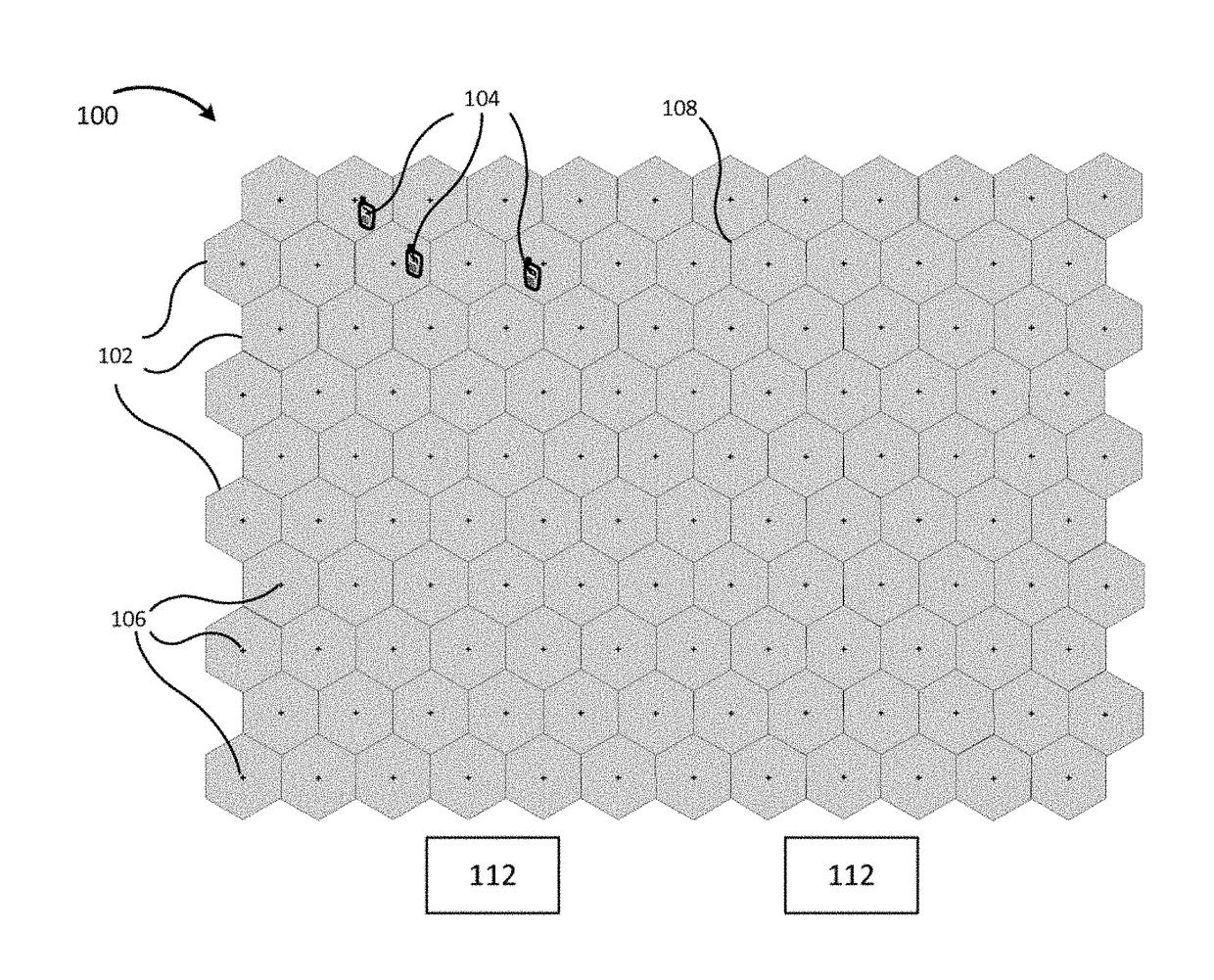
[0049]Referring now to FIG. 1 there can be seen an illustration of a service area 100 of a communication network appropriate for practicing embodiments of the present disclosure. For the purposes of the disclosure herein, the communication network will generally be referred to as a wireless communication network.

[0050]The service area 100 is depicted in FIG. 1 using a conventional honeycomb configuration of hexagonally shaped cells 102. Each individual cell, such as cell 102, represents the coverage area of one access node 106, generally represented as a cross at the approximate center of each cell 102. Alternatively the antennas of three access nodes may be placed at the intersection of three cells 108 in order to reduce the number of towers and other physical equipment needed. The antennas and physical layer of each access node 106 may be placed anywhere within or outside the cell 102 as necessary to provide the desired signal quality throughout a cell 102.

[0051]A plurality of reg...


PUM


Abstract

An apparatus for assigning a plurality of access nodes of a wireless communication network to control areas includes a processing apparatus. The processing apparatus is configured to assign each access node in the plurality of access nodes to a control area of a plurality of control areas and to determine a first control phase. The first control phase is a period of time during which the assignment of access nodes to control areas remains constant. The processing apparatus is configured to, when changing from the first control phase to a following second control phase, reassign at least a subset of access nodes which were assigned during the first control phase to a first control area to a second control area and reassign at least a subset of access nodes which were assigned during the first control phase to a third control area to the first control area.

Description

CROSS-REFERENCE TO RELATED APPLICATIONS[0001]This application is a continuation of International Application No. PCT / EP2014 / 069490, filed on Sep. 12, 2014. The disclosures of the aforementioned applications are hereby incorporated by reference in their entireties.TECHNICAL FIELD[0002]The aspects of the present disclosure relate generally to wireless communication systems and in particular to coordination of transmissions in a wireless network.BACKGROUND[0003]The proliferation of modern wireless communications devices, such as cell phones, smart phones, and tablet devices, has seen an attendant rise in demand for large multimedia data capabilities such as streaming video, TV, music, and internet access at the mobile device or user node, also referred to as the user equipment (UE). To support this ever increasing demand for higher data rates new communications techniques are being developed to take advantage of new capabilities incorporated in modern mobile devices and access nodes. T...

Claims


Application Information

Patent Timeline
Patent Type & Authority Applications(United States)
IPC IPC(8): H04W72/04H04W24/08H04W4/02
CPCH04W72/048H04B7/024H04W24/08H04W4/023H04W72/51
Inventor SALMI, JUSSIKELA, PETTERIKOUDOURIDIS, GEORGE
Owner HUAWEI TECH CO LTD
Learn More