Supercharge Your Innovation With Domain-Expert AI Agents!

Fuel Injector With Multi Tube Gas Distribution

a fuel injector and multi-tube technology, which is applied in the direction of charging feed systems, combustion processes, lighting and heating apparatus, etc., can solve problems such as deflections in the fuel injector head

Active Publication Date: 2017-07-06
SOLAR TURBINES
View PDF5 Cites 3 Cited by
  • Summary
  • Abstract
  • Description
  • Claims
  • Application Information

AI Technical Summary

Benefits of technology

The patent describes a fuel injector for a gas turbine engine. The injector includes several components that work together to evenly distribute fuel to the engine. The fuel is directed from a primary source to a secondary source using a distribution block, gas inlet passage, and primary and secondary passages. The injector head also includes an annular primary gas gallery and several fuel transfer fittings that direct fuel from the primary and secondary tubes into the gas gallery. The technical effect of this design is a more efficient and accurate delivery of fuel to the engine, which leads to improved engine performance.

Problems solved by technology

Variations in the thermal expansion of multiple fuel lines may cause deflections in the fuel injector head.

Method used


Image

  • Fuel Injector With Multi Tube Gas Distribution
  • Fuel Injector With Multi Tube Gas Distribution
  • Fuel Injector With Multi Tube Gas Distribution

Examples


Embodiment Construction

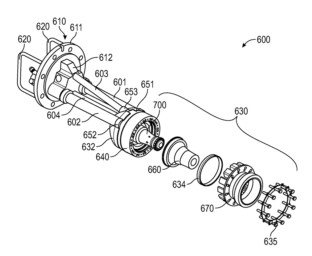
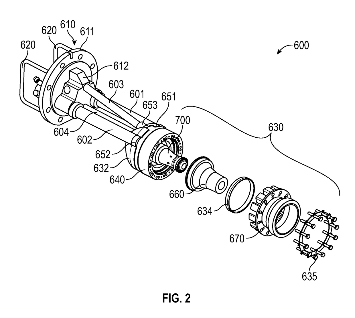
[0020]The systems and methods disclosed herein include a fuel injector for a gas turbine engine. In embodiments, the fuel injector includes a distribution block that splits the main gas fuel in three ways when supplying fuel to an injector head. The distribution block is configured to evenly supply fuel through three main gas tubes, which may result in similar thermal expansion within each tube. Matching the thermal expansion in each main gas tube may prevent deformation of the main gas tubes and may prevent deflection of the injector head.

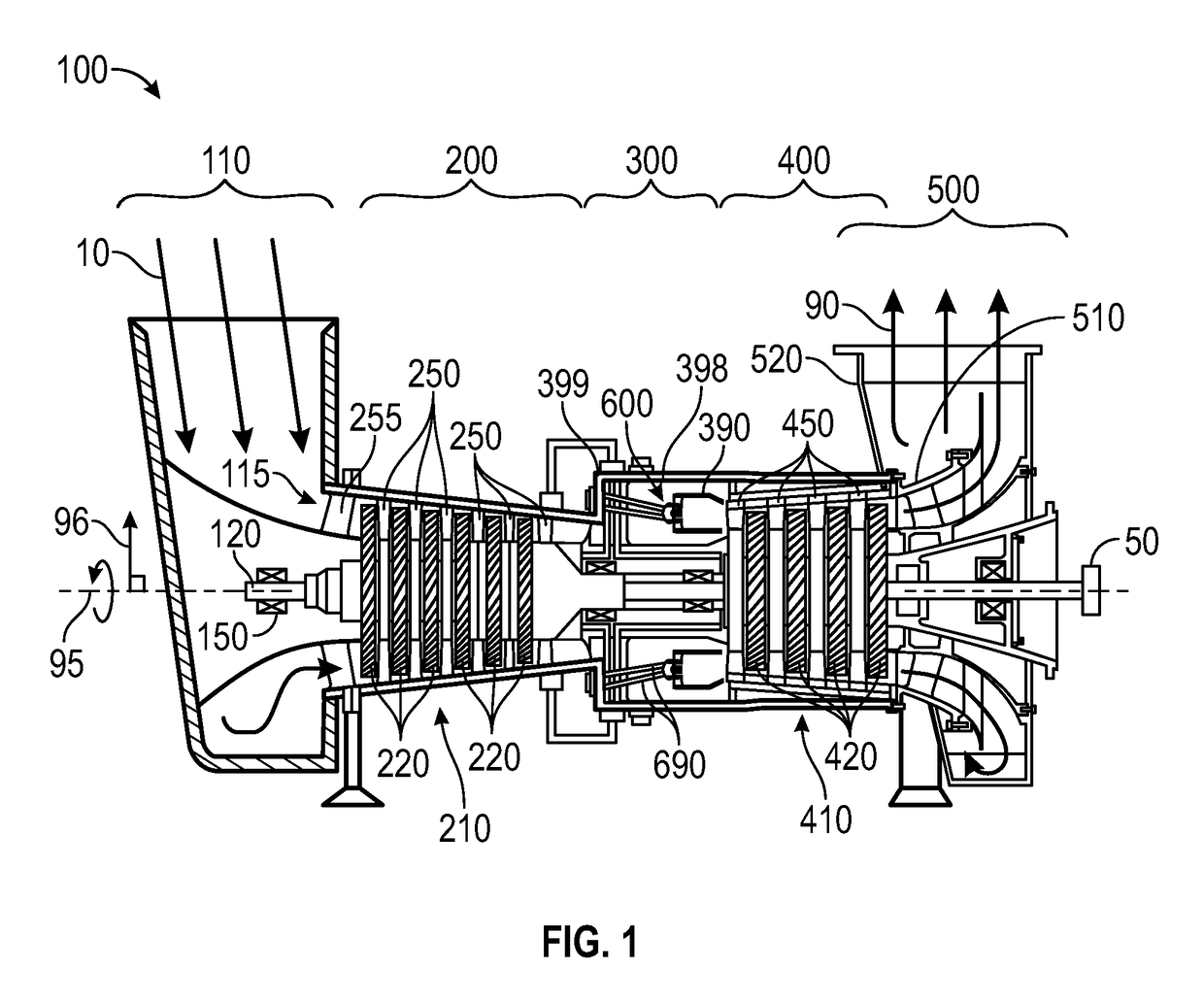
[0021]FIG. 1 is a schematic illustration of an exemplary gas turbine engine. Some of the surfaces have been left out or exaggerated (here and in other figures) for clarity and ease of explanation. Also, the disclosure may reference a forward and an aft direction. Generally, all references to “forward” and “aft” are associated with the flow direction of primary air (i.e., air used in the combustion process), unless specified otherwise. For example,...


PUM


Abstract

A fuel injector for a gas turbine engine is disclosed. The fuel injector includes a flange assembly with a distribution block, three main gas tubes, and an injector head. The distribution block evenly distributes a main gas fuel to the three main gas tubes. The injector head includes an injector body with a primary gas gallery including an annular shape. The three main gas tubes are connected in a parallel configuration between the distribution block and the primary gas gallery. The three main gas tubes are all in flow communication with the primary gas gallery and provide the main gas fuel from the same main gas fuel source.

Description

TECHNICAL FIELD[0001]The present disclosure generally pertains to gas turbine engines, and to a fuel injector with a multi-tube gas distribution circuit.BACKGROUND[0002]Gas turbine engines include compressor, combustor, and turbine sections. The combustor includes fuel injectors that supply fuel for the combustion process. Variations in the thermal expansion of multiple fuel lines may cause deflections in the fuel injector head.[0003]U.S. Pat. No. 7,121,481 to Berglund et Al. discloses a fuel injector having a chamber with a fuel inlet and a plurality of fuel outlets, and including a fuel distributor that is arranged in the chamber for the purpose of distributing fuel introduced into the chamber via the fuel inlet to the outlets. The fuel distributor includes a generally rotary symmetric distributor body.[0004]The present disclosure is directed toward overcoming one or more of the problems discovered by the inventors.SUMMARY OF THE DISCLOSURE[0005]In embodiments, a fuel injector for...

Claims


Application Information

Patent Timeline
IPC IPC(8): F02C7/22F23R3/28
CPCF02C7/222F05D2220/32F23R3/28F23R3/286F23R3/34F23R3/36F23R2900/00004F23R2900/03343
Inventor SPIVEY, SEAN KELLYCRAMB, DONALD JAMESPIPER, JAMES SCOTTRAMOTOWSKI, MICHAEL JOHN
Owner SOLAR TURBINES
Features
  • R&D
  • Intellectual Property
  • Life Sciences
  • Materials
  • Tech Scout
  • Unparalleled Data Quality
  • Higher Quality Content
  • 60% Fewer Hallucinations
Learn More