This helps you quickly interpret patents by identifying the three key elements:
Problems solved by technology
Method used
Benefits of technology
Benefits of technology
[0020]In accordance with a building assembly structure of the present invention, when a building is constructed as a multi-story building or when the frames constituting the building are extended, the frames of the building can be easily fixed. Therefore, the building can be simply constructed without the need for complicated work, and excessive time and manpower.
[0021]In addition, a bod
Problems solved by technology
Although such a structure makes it easy to assemble the basic framework of a one-story prefabricated building, it is difficult to form a multi-story prefabricated building or expand the same by changing the design thereof.
In addition
Method used
Image
Click on the blue label to locate the original text in one second.
Reading with bidirectional positioning of images and text.
Examples
Example
First Embodiment
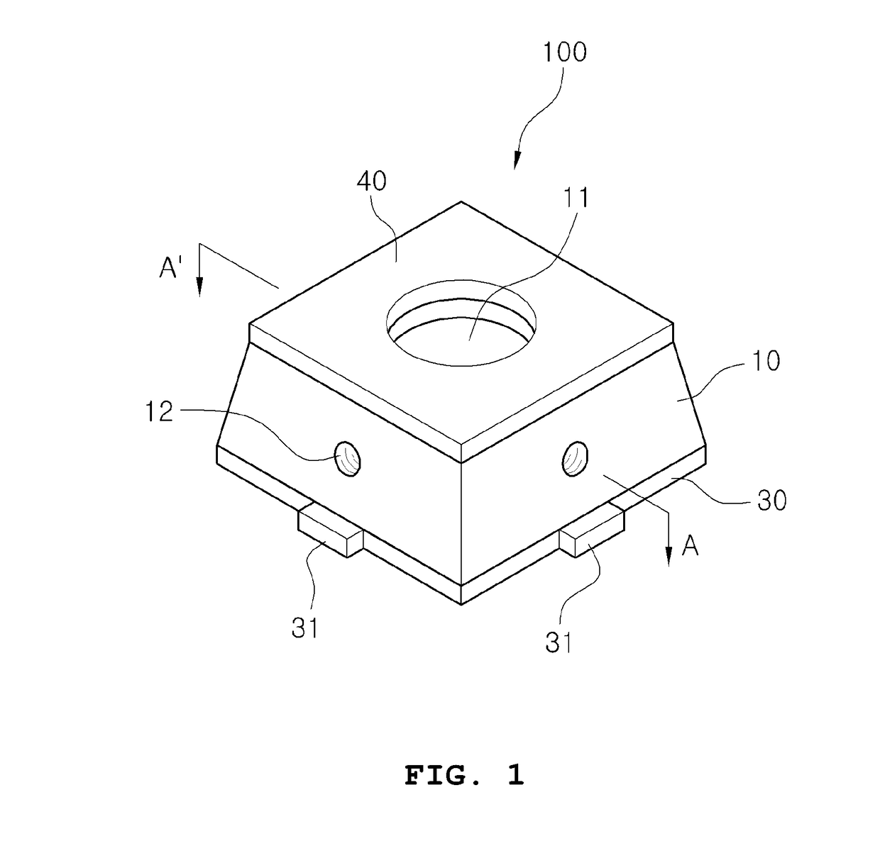
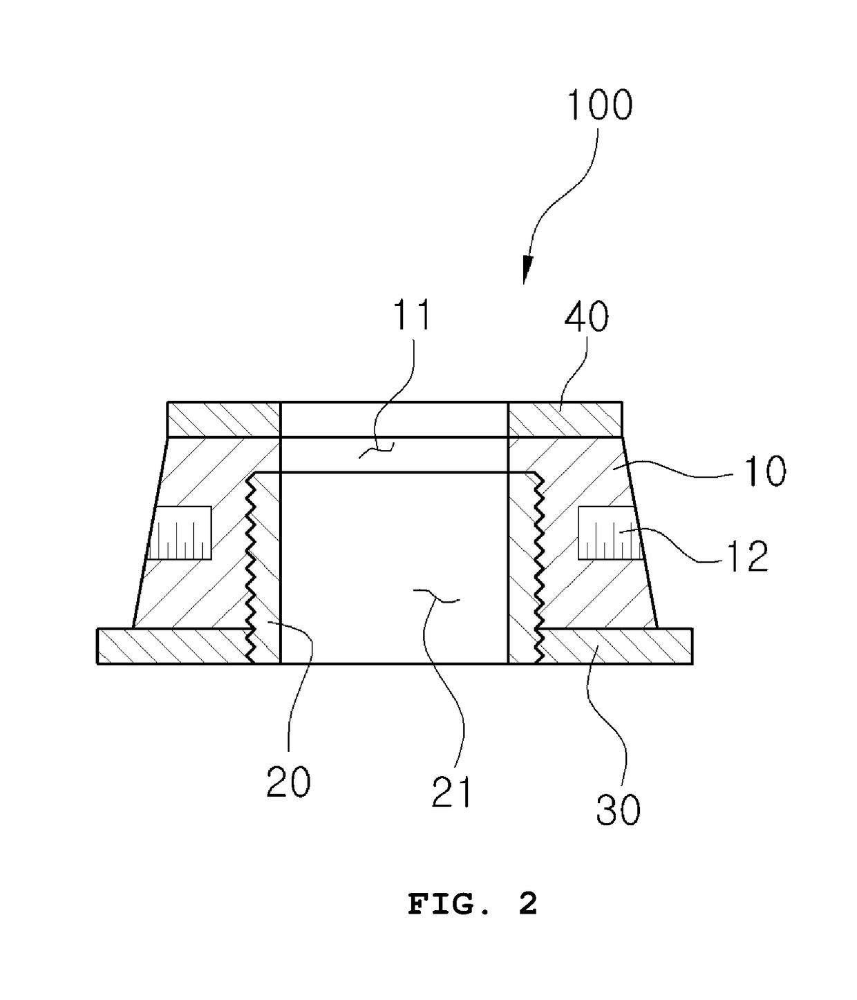
[0035]FIG. 1 is a perspective view illustrating one coupling block of a building assembly structure according to a first embodiment of the present invention. FIG. 2 is a cross-sectional view taken along line A-A′ of FIG. 1.
[0036]As illustrated in FIGS. 1 and 2, the present invention relates to a building assembly structure, and more particularly to a building assembly structure capable of fixing frames of a building on the ground and of constructing the building by extending the frames.
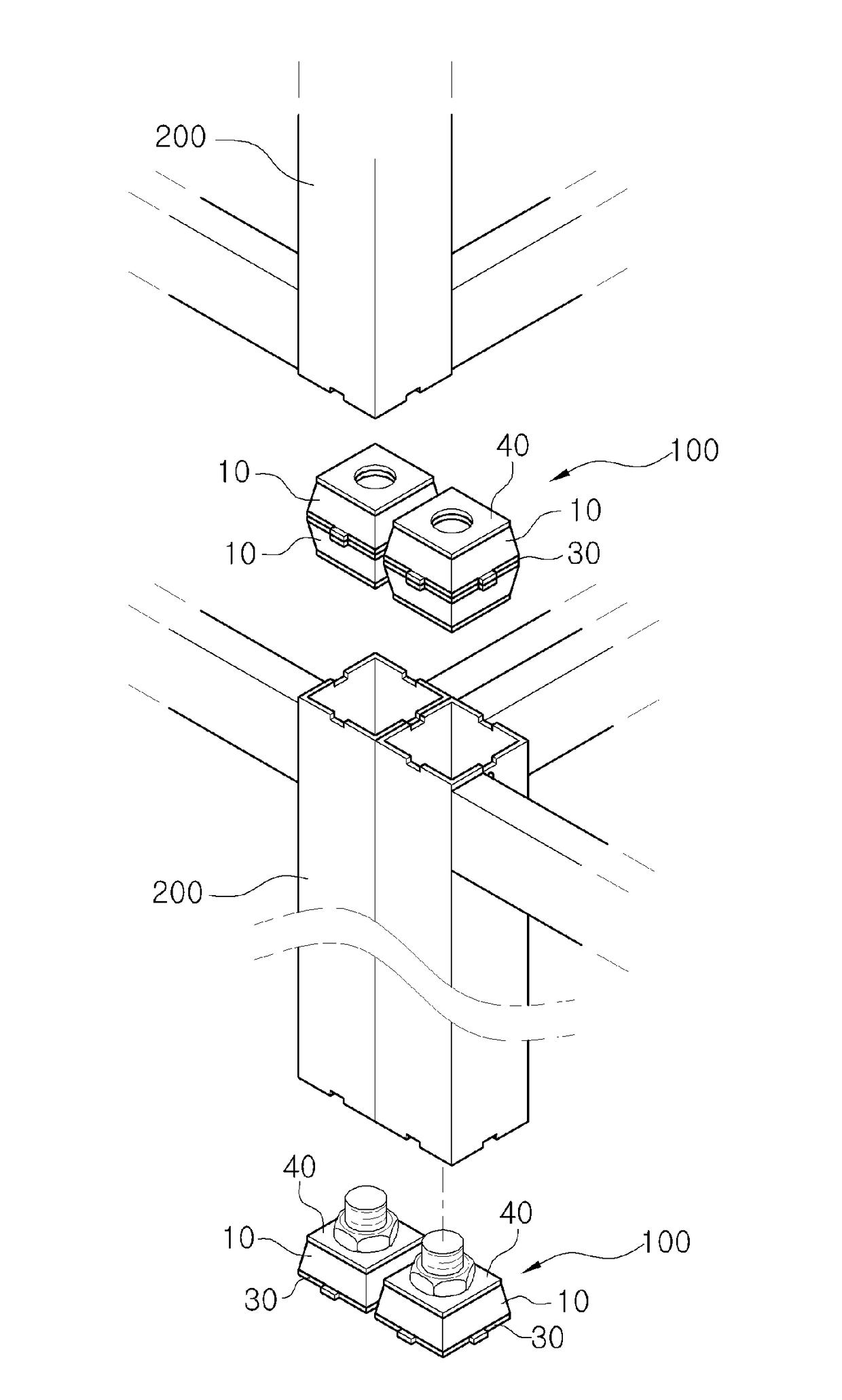
[0037]The building assembly structure includes a coupling block 100 so as to fix and support a frame 200 by installing, extending, and stacking the frame on the ground, and the coupling block 100 includes a body 10, a connection member 20, a fixing plate 30, and a vibration-proof pad 40, which are coupled to each other.
[0038]The body 10 is inserted into the end of the frame 200, and has a first through-hole 11 which passes through the upper and lower portions thereof.
[0039]The connecti...
Example
Second Embodiment
[0091]FIG. 9 is an exploded perspective view illustrating the state in which one coupling block of a building assembly structure is coupled to a frame according to a second embodiment of the present invention. FIG. 10 is a cross-sectional view illustrating the state in which the coupling block is coupled to the frame according to the embodiment of the present invention.
[0092]As illustrated in FIGS. 9 and 10, the second embodiment includes the configuration of the first embodiment, and there is further provided a frame 200 which has a fitting groove 210 formed at the end thereof in the second embodiment.
[0093]Accordingly, the fitting groove 210 consists of a plurality of fitting grooves formed at the end of the frame 200.
[0094]Here, the frame 200 is manufactured to form the basic shape of a building by welding, screwing, riveting, etc., and is then used to construct facilities such as walls and ceilings.
[0095]That is, the coupling block 100 is fixed on the ground or ...
PUM
Abstract
A building assembly structure comprises a coupling block fixed on the ground or to a frame so as to fix and extend the frame. The coupling block comprises a body has a first through-hole passing through upper and lower portions thereof, a connection member coupled to a lower portion of the first through-hole, and having a second through-hole formed therein, a fixing plate coupled to the connection member so as to be located on the lower portion of the body, and having a fixing protrusion protruding from a side thereof, and a vibration-proof pad coupled to the upper portion of the body in order to absorb load and shocks applied from above.
Description
TECHNICAL FIELD[0001]The present invention relates to a building assembly structure, and more particularly to a building assembly structure capable of fixing frames of a building on the ground and of constructing the building by extending the frames.BACKGROUND ART[0002]In general, prefabricated buildings are used to attain a short construction period and simple construction. In order to use prefabricated buildings in desired places, a basic framework is manufactured in and transported from a factory, and is then constructed to form each of facilities such as walls and ceilings.[0003]These prefabricated buildings are typical buildings, and are widely used to construct or extend buildings, studio apartments, efficiency apartments, simple houses, warehouses, schools, etc.[0004]The basic framework manufactured in the factory is configured by installing columns at the respective corners of frames consisting of floor beams and ceiling beams so as to support the floor beams and ceiling bea...
Claims
Application Information
Patent Timeline
Application Date:The date an application was filed.
Publication Date:The date a patent or application was officially published.
First Publication Date:The earliest publication date of a patent with the same application number.
Issue Date:Publication date of the patent grant document.
PCT Entry Date:The Entry date of PCT National Phase.
Estimated Expiry Date:The statutory expiry date of a patent right according to the Patent Law, and it is the longest term of protection that the patent right can achieve without the termination of the patent right due to other reasons(Term extension factor has been taken into account ).
Invalid Date:Actual expiry date is based on effective date or publication date of legal transaction data of invalid patent.

