
Methods and systems for detecting prohibited objects in a patient room

a technology for detecting prohibited objects and patient rooms, applied in the field of ##medical facilities, can solve the problems of consuming many resources, securing patients and equipment (e.g., medical devices), and unable to prevent an authorized visitor from entering the breached area of the facility, and none of these methods are necessary

Active Publication Date: 2017-07-06
CERNER INNOVATION
View PDF6 Cites 36 Cited by
  • Summary
  • Abstract
  • Description
  • Claims
  • Application Information

AI Technical Summary

Benefits of technology

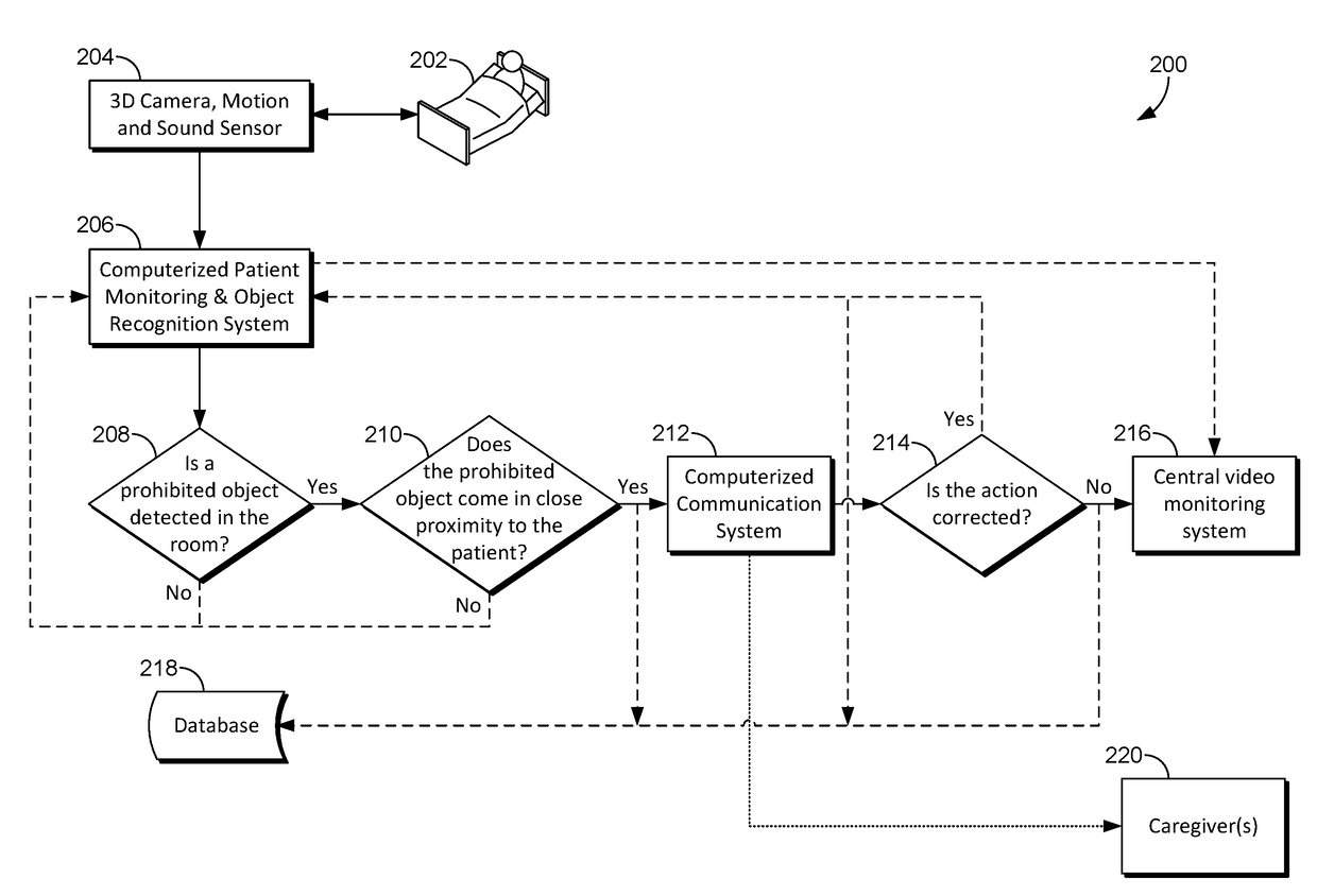
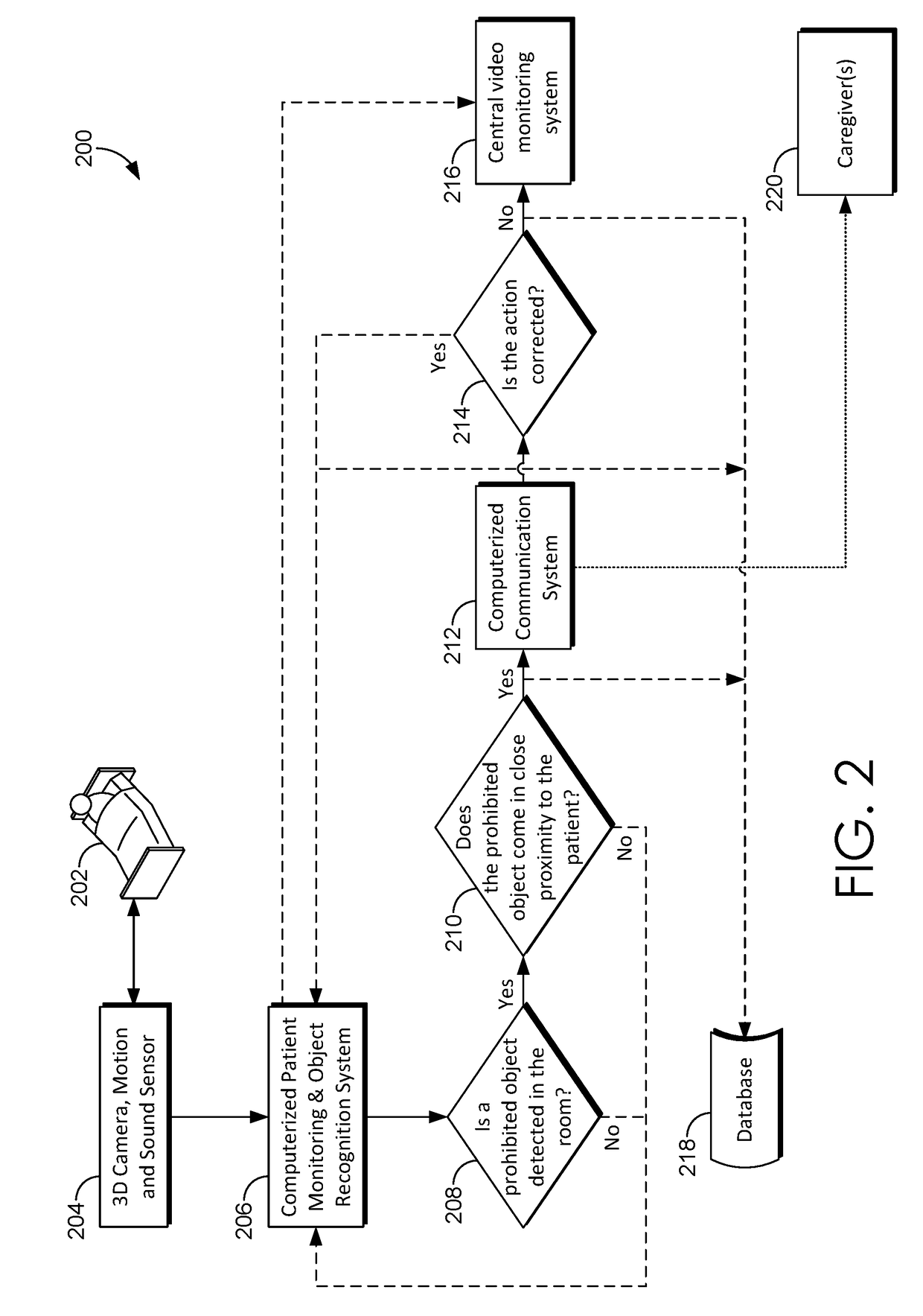
The patent text describes a system and method for detecting prohibited objects in a patient room. The system uses motion sensors to capture images of objects in the room and compares them to a database of prohibited objects to determine if the object is a prohibited object. If the object is detected as a prohibited object, the system sends an alert to designated recipients and may also display the object on a video monitoring system. The technical effect of the invention is to provide a system for identifying and managing prohibited objects in a patient room, which can improve patient safety and prevent accidents.

Problems solved by technology

Medical facilities, such as hospitals, face many challenges in addition to simply caring for patients.
For example, securing patients and equipment (e.g., medical devices) consumes many resources and current methods lack effectiveness.
However, each of these require subjective decision-making and are prone to error by the personnel monitoring the locations or assisting visitors signing a visitor log and issuing visitor badges accordingly.
Further, none of these methods necessarily prevent an authorized visitor from breaching areas of the facility where the authorized visitor is not authorized.
Additionally, in some situations, an authorized visitor may unwittingly provide contraband (e.g., some thing or some object a particular patient is not allowed) to a patient that the current methods are unable to detect.
Tracking the locations of these devices can be extremely difficult.
Accordingly, overall security for patients and equipment suffers and the many resources currently being utilized are wasted.

Method used


Image

  • Methods and systems for detecting prohibited objects in a patient room
  • Methods and systems for detecting prohibited objects in a patient room
  • Methods and systems for detecting prohibited objects in a patient room

Examples


Embodiment Construction

[0013]As noted in the Background, medical facilities, such as hospitals, face many challenges in addition to simply caring for patients. For example, securing patients and equipment (e.g., medical devices) consumes many resources and current methods lack effectiveness. In addition to requiring personnel to physically monitor locations within the facility, visitor logs and visitor badges, and radio-frequency identification (RFID) technology are often utilized to control access to certain locations within the facility. However, each of these require subjective decision-making and are prone to error by the personnel monitoring the locations or assisting visitors signing a visitor log and issuing visitor badges accordingly. Further, none of these methods necessarily prevent an authorized visitor from breaching areas of the facility where the authorized visitor is not authorized. For example, a visitor may be authorized to visit a particular patient but is not authorized to visit another...


PUM


Abstract

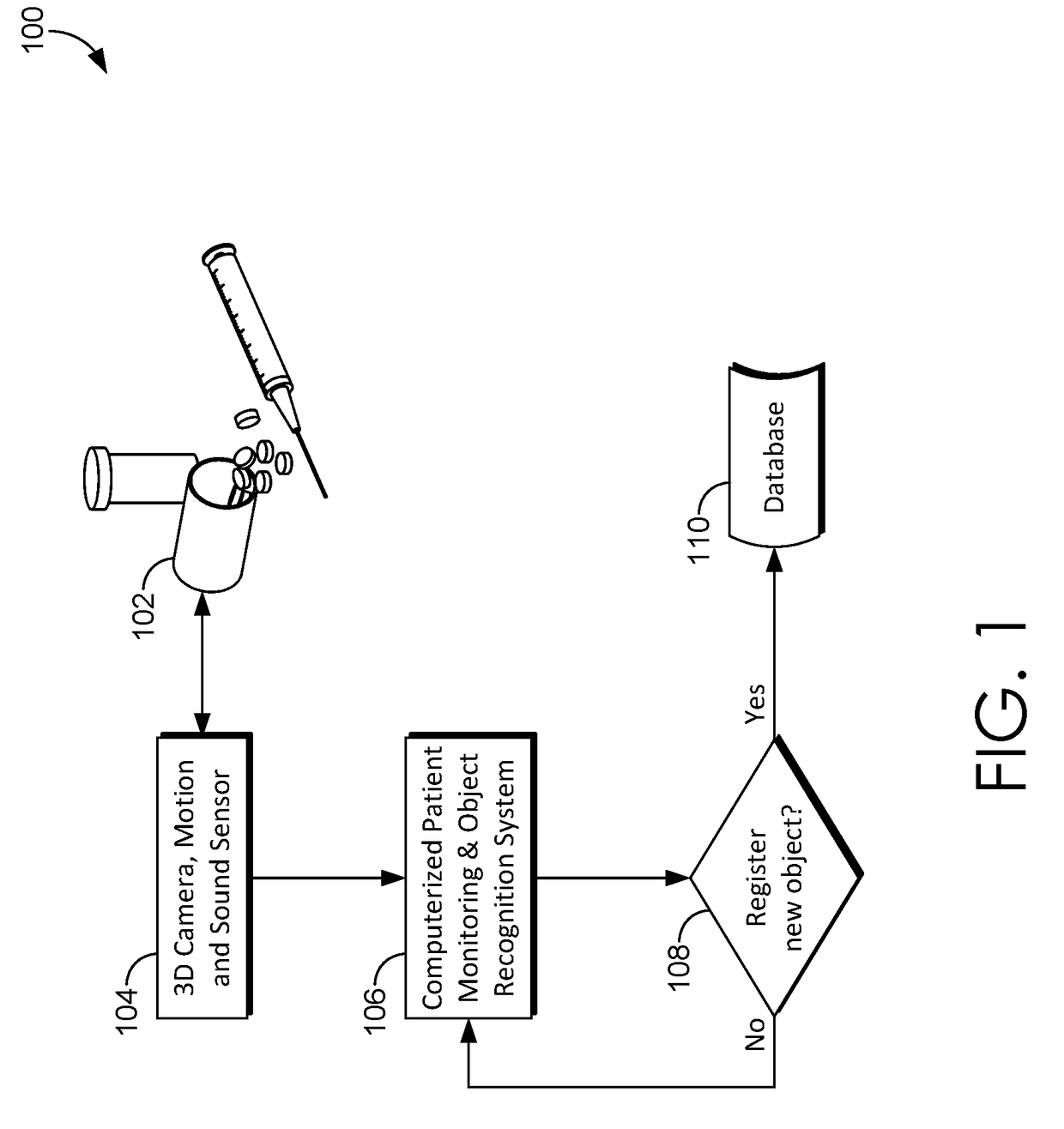
A prohibited object detection system detects prohibited objects in a patient room. An image of an object detected in a room of a patient is initially collected. The system identifies reference points on the object, for example, points along the contours of the object. The system may compare the reference points to reference points of images associated with prohibited objects. The system then determines, based on the comparison, if the object is a prohibited object. One or more designated recipients may be alerted if the object is a prohibited object. The system may also register the object in a database of prohibited objects.

Description

CROSS-REFERENCE TO RELATED APPLICATIONS[0001]This application claims the benefit of U.S. Provisional Application Ser. No. 62 / 273,735, entitled “Methods and Systems for Detecting Stroke Symptoms,” filed Dec. 31, 2015, herein incorporated by reference in its entirety, and is related to commonly assigned U.S. patent application Ser. Nos. entitled “Methods and Systems for Assigning Locations to Devices” (Attorney Docket CRNI.254459), and “Detecting Unauthorized Visitors” (Attorney Docket CRNI.265182), filed concurrently herewith on the same date.BACKGROUND[0002]Medical facilities, such as hospitals, face many challenges in addition to simply caring for patients. For example, securing patients and equipment (e.g., medical devices) consumes many resources and current methods lack effectiveness. In addition to requiring personnel to physically monitor locations within the facility, visitor logs and visitor badges, and radio-frequency identification (RFID) technology are often utilized to c...

Claims


Application Information

Patent Timeline
IPC IPC(8): G06K9/00G08B25/00G08B21/18G06K9/46G06T7/292G06T7/20H04N7/18H04N13/02G08B5/22G06F19/00
CPCG06K9/00208H04N2013/0085G08B25/009G08B21/182G06F19/3456G06T7/292G06T7/20H04N7/181H04N13/0207H04N13/0239G06K9/4604G08B21/0476G06T2207/10021G06T2207/10024G06T2207/30232G06T2200/04G08B5/22H04N7/18G06T2200/24G16H40/63G16H10/60A61B5/11G06T11/60G16H40/20G06V20/52H04N23/63H04N13/204H04N13/207G06V20/647G06V40/20G06V40/172G06V40/161G06F18/22A61B5/0077A61B5/4064A61B5/746G06F3/0482G06F3/04847G06T7/0016G06T2207/10012G06T2207/20221G06T2207/30201H04N7/183G08B13/19639A61B5/1176G06T7/0012G08B13/196G16H30/20G16H15/00G16H80/00G16H40/67G16H50/30G16H20/10
Inventor KUSENS, MICHAELKUSENS, NEIL
Owner CERNER INNOVATION
Learn More