
Method and apparatus for de-interlacing television signal

a television signal and deinterlacing technology, applied in the direction of electrical equipment, interpolation process conversion, television systems, etc., can solve the problems of great difficulty in de-interlacing algorithm direction determination in motion scenarios, and the inability to perform well in interpolation based on direction determination, so as to improve the accuracy of detecting direction, high precision, and the effect of pixel valu

Active Publication Date: 2017-07-06
SPREADTRUM COMM (SHANGHAI) CO LTD
View PDF12 Cites 2 Cited by
  • Summary
  • Abstract
  • Description
  • Claims
  • Application Information

AI Technical Summary

Benefits of technology

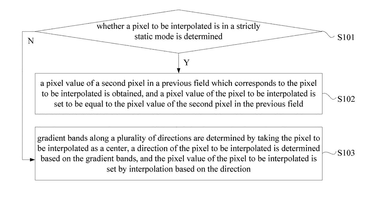
The present disclosure provides a method and apparatus for de-interlacing a television signal to improve the accuracy of pixel values. The method involves determining if a pixel to be interpolated is in a strictly static mode or a moving mode. In the strictly static mode, a pixel value of a previous field is obtained and used as the pixel value of the pixel to be interpolated. In the moving mode, gradient bands along multiple directions are determined as a center and used to determine the direction of the pixel to be interpolated. This allows for more accurate detection of the pixel's direction, resulting in a more accurate pixel value. Overall, this method and apparatus improve the accuracy of pixel values and enhance the quality of the television signal.

Problems solved by technology

(1) When hardware sources are limited, for example, there are only two lines of data in a vertical direction (that is, only one row of pixels in a top filed have known pixel values and only one row of pixels in a bottom field have known pixel values, respectively), almost no algorithm can ensure accuracy of direction determination. Further, to some details, although related data are many enough, interpolation can not be well performed based on direction determination. That is because the details do not have a clear direction (such as some corners in characters). In fact, a portion of images in a video may retain absolutely static or relatively static (global motion).
(2) Direction determination in a motion scenario is great difficulty in de-interlacing algorithm, especially when a direction of images presents a relatively small angle.

Method used


Image

  • Method and apparatus for de-interlacing television signal
  • Method and apparatus for de-interlacing television signal
  • Method and apparatus for de-interlacing television signal

Examples


Embodiment Construction

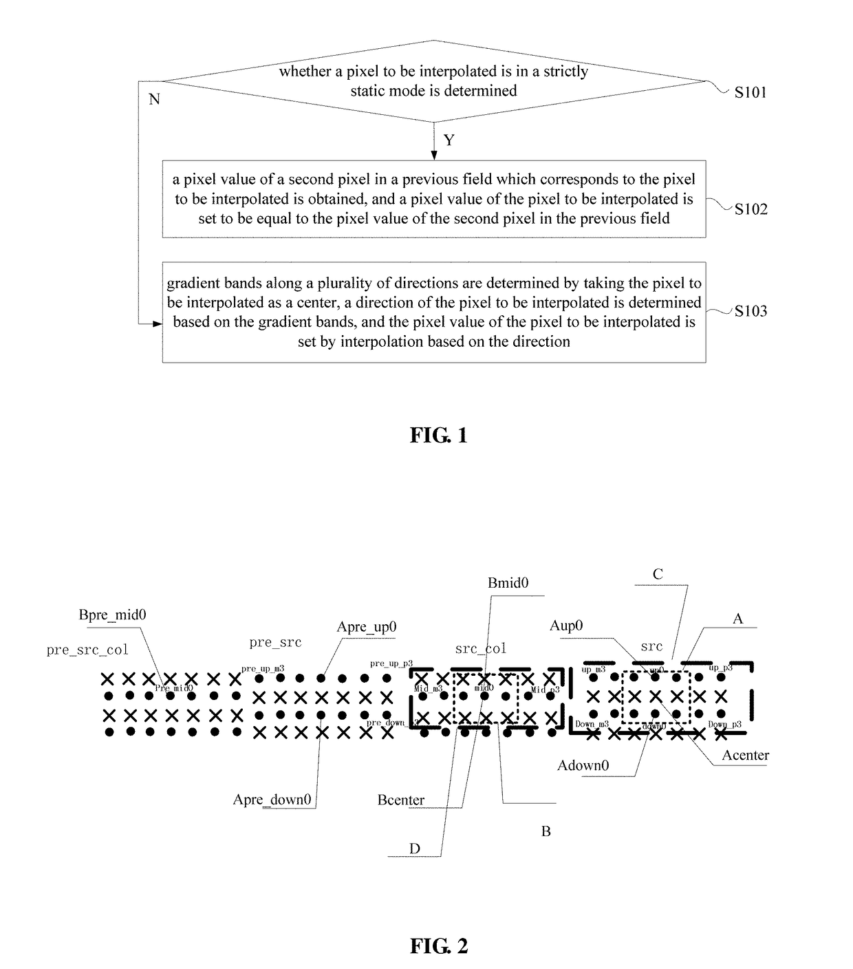
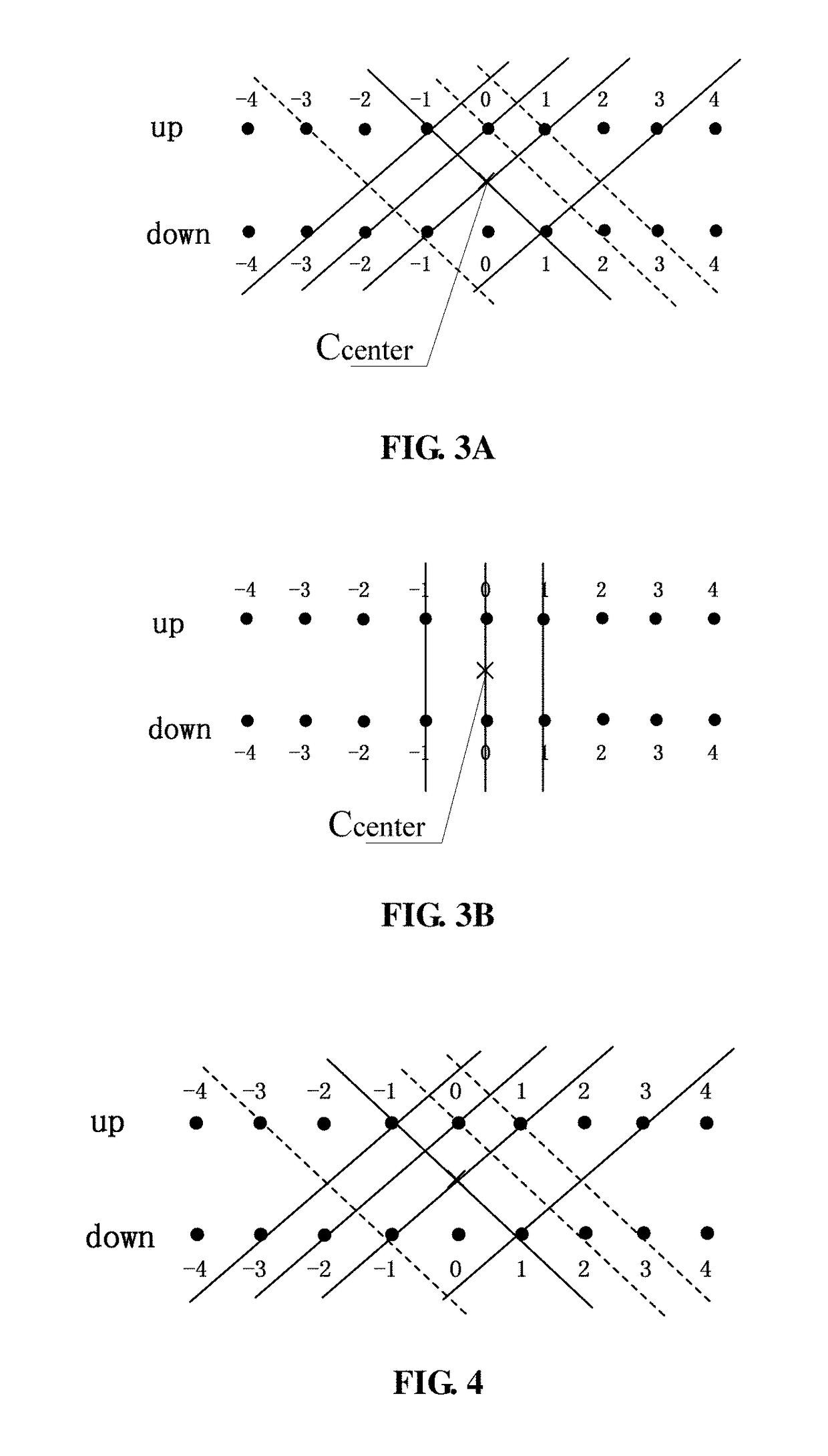
[0038]As described in the background, in existing techniques, directions of missing pixels are deduced based on known pixels, and pixel values of the missing pixels are obtained by performing interpolation to the known pixels at the deduced directions. Regarding the disadvantage (1) described in the background, embodiments of the present disclosure provide a de-interlacing algorithm based on detection of strictly static scenario. Regarding the disadvantage (2) described in the background, embodiments of the present disclosure provide a banded gradient calculating method and a method for downsampling gradient bands to simplify them, which can obtain better performance at the cost of a little greater computational complexity and a little logics.

[0039]Embodiments of present disclosure will be described clearly in detail in conjunction with accompanying drawings. The embodiments below are only described for example, and there are many other possible embodiments. Based on the embodiments...


PUM


Abstract

Method and apparatus for de-interlacing a television signal are provided. The method includes: determining whether a pixel to be interpolated is in a strictly static mode; if it is in the strictly static mode, obtaining a pixel value of a first pixel in a previous field which corresponds to the pixel to be interpolated, and setting a pixel value of the pixel to be interpolated to be equal to the pixel value of the first pixel; if it is not in the strictly static mode, determining gradient bands along a plurality of directions by taking the pixel to be interpolated as a center, determining a direction of the pixel to be interpolated based on the gradient bands, and setting the pixel value of the pixel to be interpolated by interpolation based on the direction. Accuracy of the pixel value of the pixel to be interpolated may be improved.

Description

CROSS-REFERENCE TO RELATED APPLICATIONS[0001]The present application claims priority to Chinese patent application No. 201511025765.1, filed on Dec. 30, 2015, and entitled “METHOD AND APPARATUS FOR DE-INTERLACING TELEVISION SIGNAL”, and the entire disclosure of which is incorporated herein by reference.FIELD OF THE DISCLOSURE[0002]The present disclosure generally relates to signal processing technology field, and more particularly, to a method and apparatus for de-interlacing a television signal.BACKGROUND OF THE DISCLOSURE[0003]In transmission and reception of television signals, interlaced scan is generally employed. This technique uses two fields to create a frame. One field called top field contains all odd-numbered lines in a television image; the other called bottom field contains all even-numbered lines in the television image. After the interlaced scan to the top field and the bottom field, scan data corresponding to the top field and scan data corresponding to the bottom da...

Claims


Application Information

Patent Timeline
Patent Type & Authority Applications(United States)
IPC IPC(8): H04N7/01
CPCH04N7/0137H04N7/012
Inventor ZHOU, HONGWEI, HULUO, XIAOWEIWANG, SENCHEN, MINJIEZHU, JUNXUE, DUANLIN, FUHUEI
Owner SPREADTRUM COMM (SHANGHAI) CO LTD
Learn More