
LED tube lamp including light strip including a pad and an opening formed on the pad

Active Publication Date: 2017-07-06
JIAXING SUPER LIGHTING ELECTRIC APPLIANCE
View PDF0 Cites 12 Cited by
  • Summary
  • Abstract
  • Description
  • Claims
  • Application Information

AI Technical Summary

Benefits of technology

The present invention provides an LED tube lamp with various features and improvements. The lamp includes a tube, a terminal adapter circuit, a first rectifying circuit, a filtering circuit, an LED lighting module, an anti-flickering circuit, and an over voltage protection circuit. The filtering circuit filters the external driving signal to generate a filtered signal, which is then sent to the LED lighting module for driving the LEDs. The anti-flickering circuit prevents flickering of the LEDs by detecting the filtered signal and clamping the voltage level of the signal. The over voltage protection circuit detects the filtered signal and clamps the voltage level of the signal if it exceeds a set level. The LED tube lamp may also include a second rectifying circuit for concurrent rectification, two filament-simulating circuits, and various improvements such as over voltage protection, anti-flickering circuit, and more.

Problems solved by technology

Therefore, the LED tube lamp affects the resonant of the resonant circuit and so causes compatible problems.
However, the conventional LED driving circuit can not supply the filament detection and so can not light with the pre-heat electronic ballast.
In addition, the electronic ballast is effectively a current source, and it easily results in the problems of over current, over voltage, under current and the under voltage when being used to be a power supply of the LED tube lamp.
The LED tube lamp may not provide stable lighting and even the electrical device therein may be damaged.
Moreover, a transient flicker appears after the user turned off the power and it makes the user discomfort.

Method used


Image

  • LED tube lamp including light strip including a pad and an opening formed on the pad
  • LED tube lamp including light strip including a pad and an opening formed on the pad
  • LED tube lamp including light strip including a pad and an opening formed on the pad

Examples


Embodiment Construction

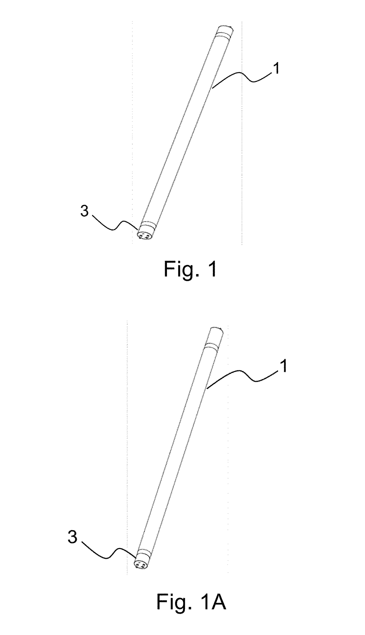
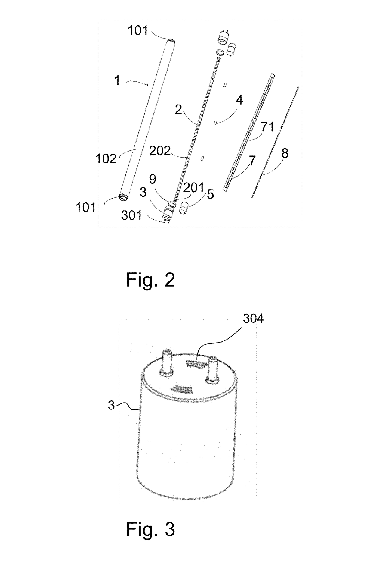
[0102]The present disclosure provides a novel LED tube lamp based on the glass made tube to solve the abovementioned problems. The present disclosure will now be described in the following embodiments with reference to the drawings. The following descriptions of various embodiments of this invention are presented herein for purpose of illustration and giving examples only. It is not intended to be exhaustive or to be limited to the precise form disclosed. These example embodiments are just that—examples—and many implementations and variations are possible that do not require the details provided herein. It should also be emphasized that the disclosure provides details of alternative examples, but such listing of alternatives is not exhaustive. Furthermore, any consistency of detail between various examples should not be interpreted as requiring such detail—it is impracticable to list every possible variation for every feature described herein. The language of the claims should be re...


PUM


Abstract

An LED tube lamp is disclosed. The LED tube lamp includes a filtering circuit, an LED lighting module, and an anti-flickering circuit. The filtering circuit is configured to filter a rectified external driving signal. The LED lighting module has an LED module, and is configured to generate a driving signal, and the LED module is configured to receive the driving signal to emit light. The LED module is formed on an LED light strip, which includes at least a first pad connected to the filtering circuit, and at least an opening formed on the first pad. The anti-flickering circuit is configured to reduce flickering effect in light emission of the LED module. The LED tube lamp further includes a conduction-delaying circuit; a first rectifying circuit and at least a fuse; or first and second filament-simulating circuits respectively coupled to two opposite ends of the lamp tube.

Description

CROSS-REFERENCE TO RELATED APPLICATIONS[0001]The present application is a Continuation application of U.S. patent application Ser. No. 15 / 065,890, filed Mar. 10, 2016, the contents of which are incorporated herein by reference in their entirety, and which is a Continuation-in-part application of U.S. patent application Ser. No. 14 / 865,387, filed Sep. 25, 2015, the contents of which are incorporated herein by reference in their entirety, and which claims priority under 35 U.S.C. §119 to the following Chinese Patent Applications Nos. CN 201510104823.3 filed on 2015 Mar. 10; CN 201510136796.8 filed on 2015 Mar. 27; CN 201510259151.3 filed on 2015 May 19; CN 201510338027.6 filed on 2015 Jun. 17; CN 201510373492.3 filed on 2015 Jun. 26; CN 201510482944.1 filed on 2015 Aug. 7; CN 201510483475.5 filed on 2015 Aug. 8; CN 201510486115.0 filed on 2015 Aug. 8; CN 201510555543.4 filed on 2015 Sep. 2; CN 201510557717.0 filed on 2015 Sep. 6; and CN 201510595173.7 filed on 2015 Sep. 18, the disclo...

Claims


Application Information

Patent Timeline
IPC IPC(8): H05B33/08F21V23/06F21V3/04F21K9/278F21K9/272H05B44/00
CPCH05B33/0845H05B33/089H05B33/0809F21K9/278F21Y2115/10F21V3/0418F21V23/06F21Y2103/10F21K9/272F21V3/061H05B45/40H05B45/50H05B45/59
Inventor XIONG, AIMINGHU, HECHENYE, QIFENG
Owner JIAXING SUPER LIGHTING ELECTRIC APPLIANCE
Features
  • Generate Ideas
  • Intellectual Property
  • Life Sciences
  • Materials
  • Tech Scout
  • Unparalleled Data Quality
  • Higher Quality Content
  • 60% Fewer Hallucinations
Learn More