Door handle mounting device for a motor vehicle

a technology for mounting devices and doors, applied in the direction of building locks, constructions, locks, etc., to achieve the effect of simple and economical construction, simple design, and simple installation of door handle mounting devices

Inactive Publication Date: 2017-07-13
HUF HULSBECK & FURST GMBH & CO KG
View PDF1 Cites 1 Cited by
  • Summary
  • Abstract
  • Description
  • Claims
  • Application Information

AI Technical Summary

Benefits of technology

[0010]In another design, the invention provides that at least one retaining arm is formed on the locking element, by means of which the at least one spring element is retained on the locking element. The spring element, or the return element, respectively, is thus not attached to the cylinder core or the door handle mount, but to the locking element instead, thus simplifying the installation of the door handle mounting device, because the return element can be pre-installed on the locking element, before the locking element itself is rotatably installed on the door handle mount.
[0011]In another design, the invention provides that both the first spring leg as well as the second spring leg each bear against a bearing lip. The bearing lip serves as a stationary reference point thereby, having a structurally particularly simple design.
[0012]In order that the two spring legs can be spring loaded against one another, and can apply the return force, it is of particular advantage in another design of the invention when both the first spring leg as well as the second spring leg each bear against a movement lip formed on the locking element, such that when the actuator moves from the initial position into the unlocking position or into the locking position, the two spring legs are spring loaded against one another, and apply the return force.
[0013]With respect to a simple and economical construction, it is advantageous in the design of the invention when at least one guide arm is formed on the door handle mount, which extends in the longitudinal direction of the housing, and engages behind the peripheral edge of the wheel-like locking element, at least in the initial position, and at least during a movement from the initial position into the unlocking position or into the locking position.
[0014]In order to increase the installation simplicity, in another design the invention provides that the peripheral edge of the wheel-like locking element has at least one installation recess, wherein the locking element can be rotated into an installation position in order to be installed on the door handle mount, in which position the at least one guide arm is disposed such that it is flush with the at least one installation recess, and does not engage behind the peripheral edge of the wheel-like or disk-shaped locking element.
[0015]Lastly, in another design, the invention provides that a lever arm is formed on the wheel-like locking element, which extends beyond the peripheral edge of the locking element, and can be coupled to the lock of the motor vehicle. The entire structural unit, comprising the locking device, the locking element, which is placed on the actuator for the locking device, and the return element, which is non-rotatably attached to the locking element, and bears against the door handle mount, can be designed with a reduced installation depth, which is further supported by the lever arm, which extends radially over the peripheral edge of the locking element.

Problems solved by technology

This is accompanied with the disadvantage that the depth of the door of the motor vehicle must take this installation depth into account.

Method used


Image

  • Door handle mounting device for a motor vehicle
  • Door handle mounting device for a motor vehicle
  • Door handle mounting device for a motor vehicle

Examples


Embodiment Construction

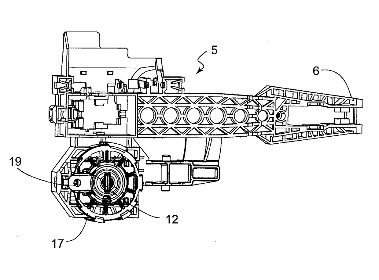
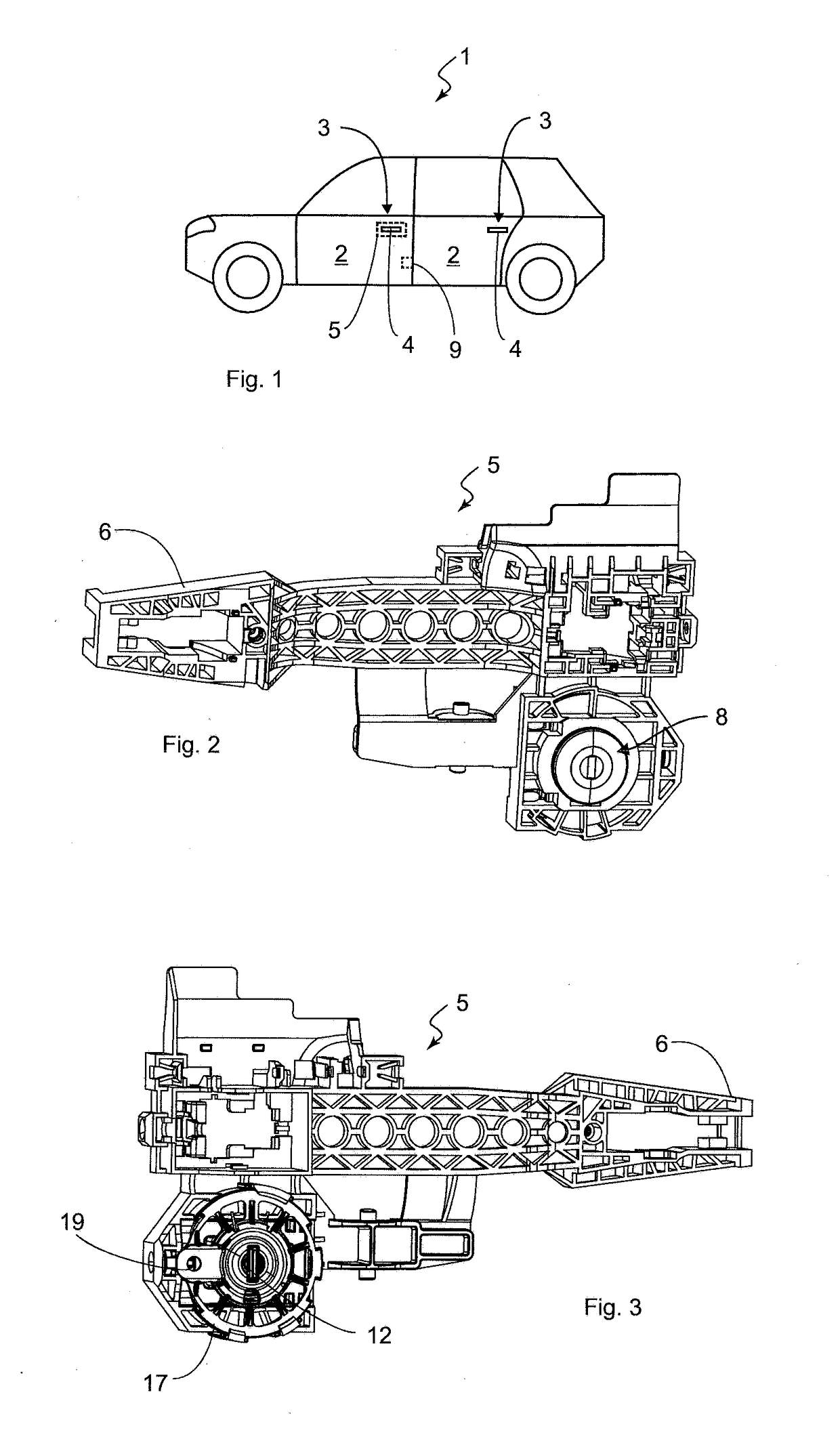
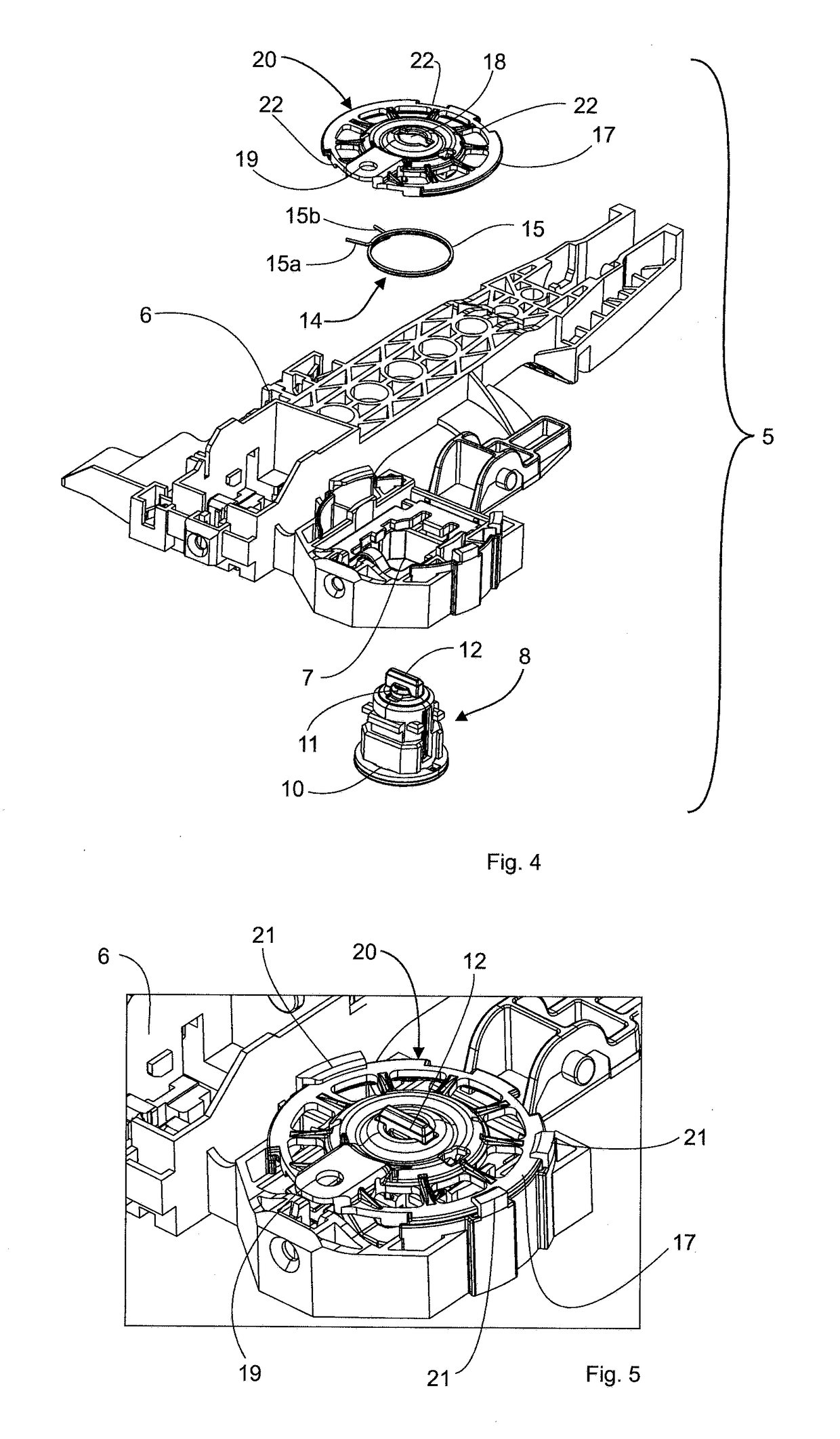
[0032]In FIG. 1 a vehicle, or motor vehicle 1, respectively, is depicted by way of example in the form of a passenger car, having four doors 2 (two of which are visible in FIG. 1), which can be opened via a door handle assembly 3 and in particular using a door handle, or a handle 4, respectively. The handle 4 is moveably supported on a door handle mounting device 5 that is only schematically indicated for the driver door 2. The door handle mounting device 5 is shown in FIG. 2 in a front view, whereas a rear view of the door handle mounting device 5 is depicted in FIG. 3. The door handle mounting device 5 has a frame-like door handle mount 6, which is designed in the known manner for the attachment of the handle 4, and is attached to the inside of the door 2 by means of screw connections, not shown in detail, wherein the handle 4 is disposed on the outside of the door 2. The door handle mount 6 is substantially formed by a frame structure for the purpose of material reduction, having...


PUM


Abstract

A door handle mounting device for a motor vehicle includes a door handle mount with a receiving space and a closing device attached to the door handle mount which is accommodated at least in part in the receiving space. The closing device includes a housing and a cylinder core rotatably supported in the housing and an actuator that is non-rotatably connected to the cylinder core for actuating a lock of the motor vehicle. A return element which exerts a return force on the actuator retains the actuator in its initial position or returns it thereto. The actuator is adapted to be rotated against the return force of the return element from the initial position and to an unlocking position or into a locking position. The return element is disposed lying radially surrounding the cylinder core and outside of the housing.

Description

[0001]This application claims the benefit of U.S. Provisional Application No. 62 / 278,129, filed Jan. 13, 2016, and is incorporated herein by reference in its entirety.BACKGROUND[0002]The invention relates to a door handle mounting device for a motor vehicle, having a door handle mount with a receiving space, a locking device that can be attached to the door handle mount, which is accommodated, at least in part, in the receiving space, and which comprises at least a housing, a cylinder core rotatably supported in the housing, and an actuator that is non-rotatably connected to the cylinder core, for actuating a lock of the motor vehicle, and having a return element that exerts a return force on the actuator that retains the actuator in the initial position, or returns it thereto, wherein the actuator can be rotated against the return force of the return element, from the initial position, into an unlocking position or into a locking position.[0003]A door handle mounting device of the ...

Claims


Application Information

Patent Timeline
Patent Type & Authority Applications(United States)
IPC IPC(8): E05B85/06E05B79/06
CPCE05B79/06E05B85/06E05B79/22E05B2009/047E05B2015/041
Inventor HANSEN, JEFFREY KENNETHKOZAK, EUGENEKAYA, SUAT
Owner HUF HULSBECK & FURST GMBH & CO KG
Why Eureka
Try Eureka