

Device for welding profiled elements in plastic material, in particular PVC
a technology of plastic material and profiled elements, applied in the field of plastic material profiled elements, can solve the problems of large waste of materials to be removed, complicated removal of said bead, and the existence of known welding devices briefly described, etc., and achieve the effect of reducing space, fast and cheap
- Summary
- Abstract
- Description
- Claims
- Application Information
AI Technical Summary
Benefits of technology
Problems solved by technology
Method used
Image

Examples
Embodiment Construction
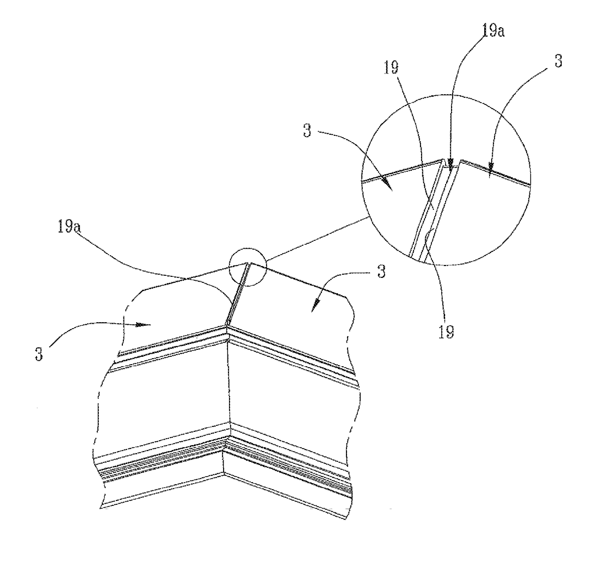
[0013]In this context, the technical aim underlying the present invention is to propose a device for welding profiled elements in plastic material, in particular PVC, which overcomes the drawbacks of the above-mentioned state of the art.
[0014]In particular, the object of the present invention is to place at disposal a device for welding two profiled elements made in plastic material, in particular PVC able to eliminate all subsequent additional operations suitable for removing the welding bead.
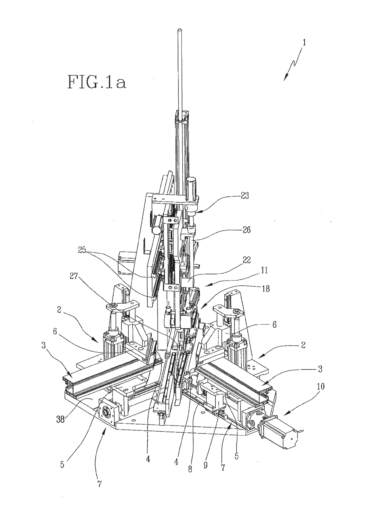
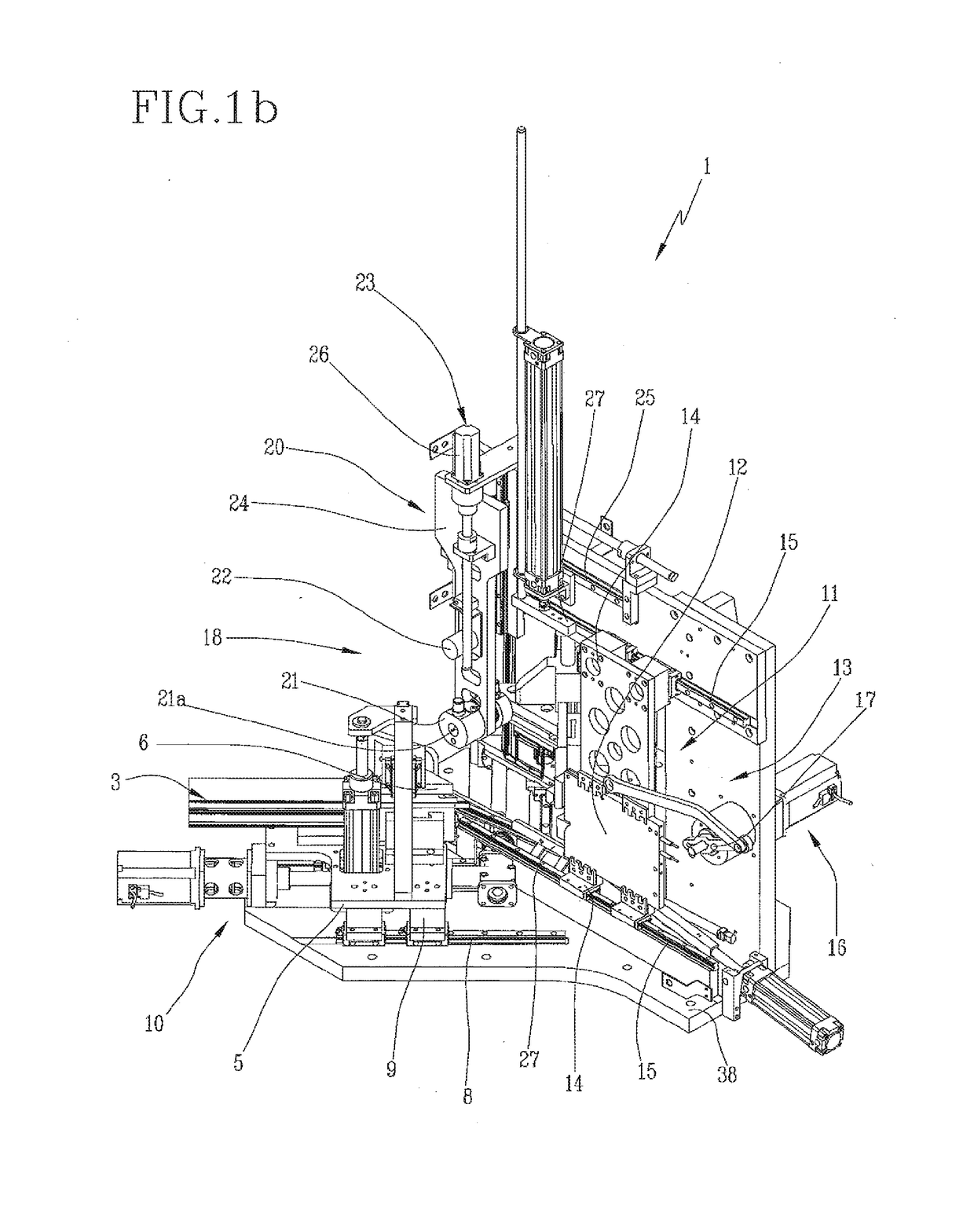
[0015]Another object of the present invention is to envisage a device for welding profiled elements in plastic material, in particular PVC, that is fast, cheap and with reduced space.
[0016]The above objects are achieved by a device for welding profiled elements in plastic material, in particular PVC, comprising the technical specifications stated in any of the enclosed claims.
BRIEF DESCRIPTION OF THE DRAWINGS
[0017]Other characteristics and advantages of the present invention will become more e...
PUM
| Property | Measurement | Unit |
|---|---|---|
| angle | aaaaa | aaaaa |
| angle | aaaaa | aaaaa |
| thickness | aaaaa | aaaaa |
Abstract
Description
Claims
Application Information