
Method and device for welding profiled elements in plastic material, in particular PVC

Active Publication Date: 2015-04-16
GRAF SYNERGY
View PDF3 Cites 1 Cited by
  • Summary
  • Abstract
  • Description
  • Claims
  • Application Information

AI Technical Summary

Benefits of technology

The present invention aims to offer a method and device for welding plastic profiled elements, particularly PVC, that can eliminate the need for additional operations to remove the welding bead. Additionally, the invention aims to provide a fast, cost-effective, and space-efficient method for welding plastic profiled elements.

Problems solved by technology

The known welding devices briefly described do however have major drawbacks mainly tied to the formation of the above-mentioned welding bead.
It must in fact be considered that the welding zone of the PVC profiled elements is not perfectly uniform and consequently, to make the profiled elements even, a lot of material is melted with the consequent formation of an abundant bead, and there is consequently a lot of waste material to be removed.
Furthermore, in the case of spoked profiled elements, the removal of said bead is very complicated.
Furthermore, the machinery used for the above-mentioned finishing operations is cumbersome and particularly expensive.
This results in the need to sustain additional costs and work times because of the presence of further cumbersome equipment and tools.

Method used


Image

  • Method and device for welding profiled elements in plastic material, in particular PVC
  • Method and device for welding profiled elements in plastic material, in particular PVC
  • Method and device for welding profiled elements in plastic material, in particular PVC

Examples


Embodiment Construction

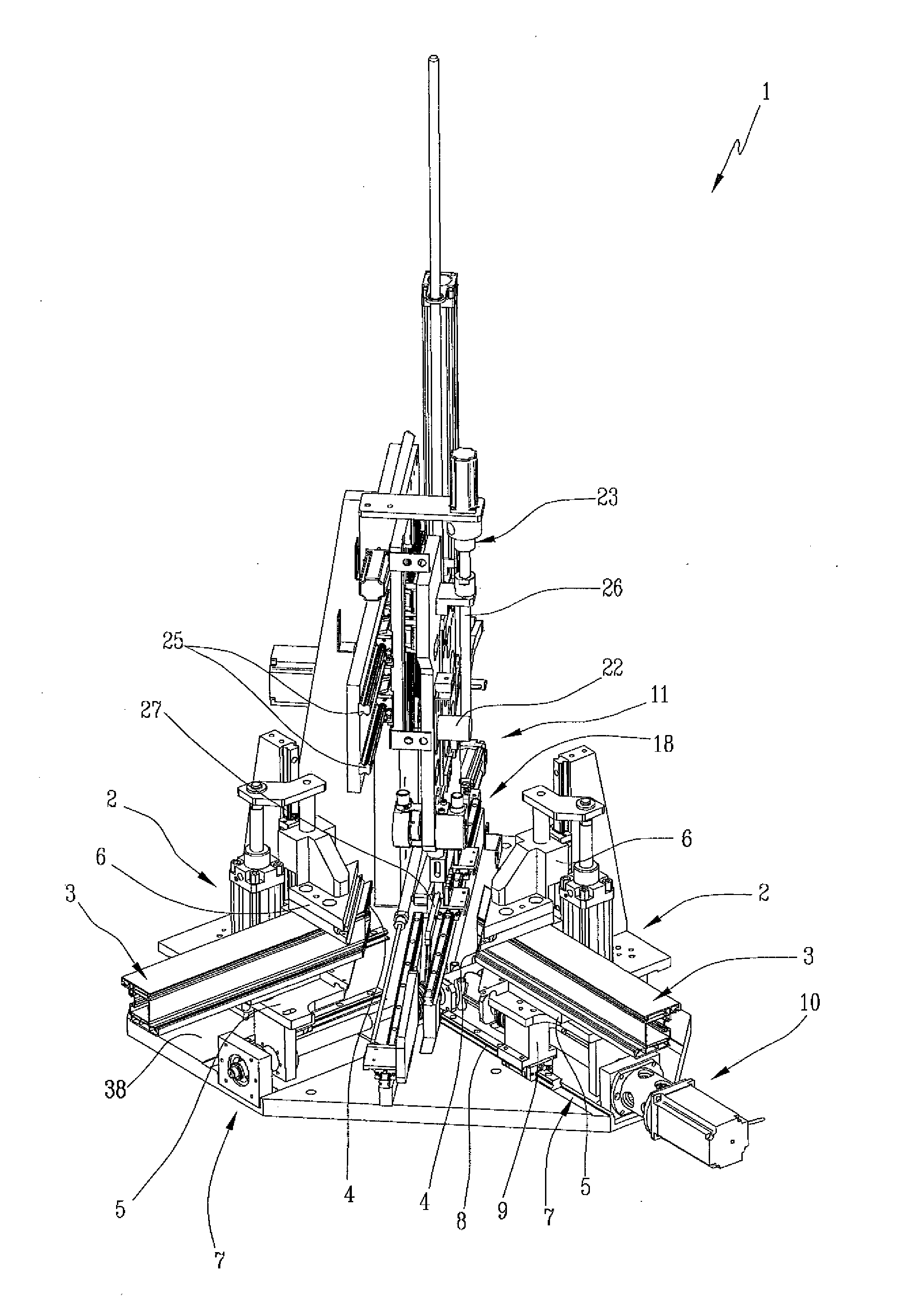
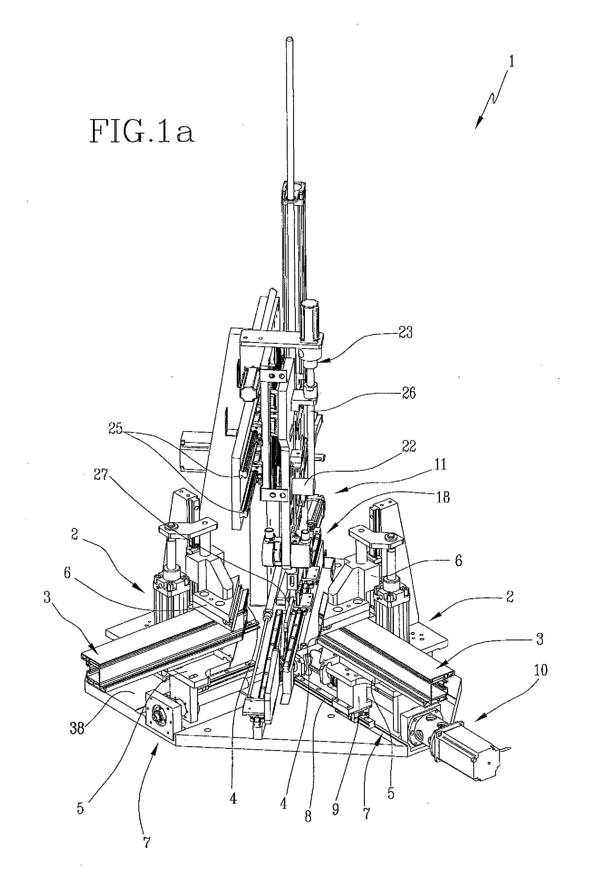
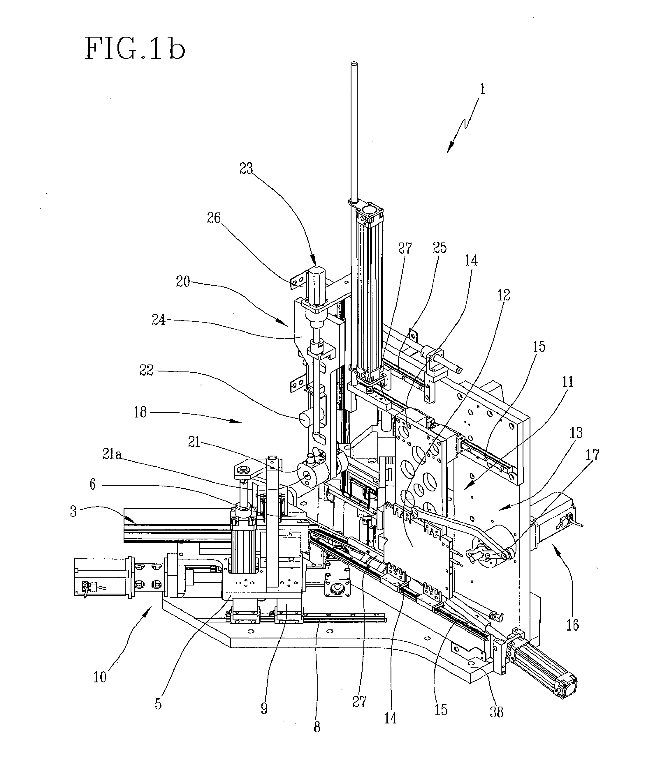
[0013]In this context, the technical aim underlying the present invention is to propose a method and relative device for welding profiled elements in plastic material, in particular PVC, which overcomes the drawbacks of the above-mentioned state of the art.

[0014]In particular, the object of the present invention is to place at disposal a method and relative device for welding two profiled elements made in plastic material, in particular PVC able to eliminate all subsequent additional operations suitable for removing the welding bead.

[0015]Another object of the present invention is to envisage a method for welding profiled elements in plastic material, in particular PVC, that is fast, cheap and with reduced space.

[0016]The above objects are achieved by a method and relative device for welding profiled elements in plastic material, in particular PVC, comprising the technical specifications stated in any of the enclosed claims.

BRIEF DESCRIPTION OF THE DRAWINGS

[0017]Other characteristic...


PUM

PropertyMeasurementUnit
Angleaaaaaaaaaa

Abstract

A method for welding profiled elements in plastic material, includes the steps of: preparing two profiled elements, arranged with respective zones to be facing one another; making a groove in correspondence to at least one zone, by a removal operation on a peripheral edge of at least one profiled element; heating the zones to be welded; coupling the zones to be welded to one another, pressing the profiled elements one against the other so as to keep the zones to be welded in reciprocal contact. The coupling step includes: melting the zones to be welded into one another in order to define a welding bead; making a containing compartment defined by the groove, the welding bead being made internally of the containing compartment; and arranging a containing presser in correspondence to the containing compartment for preventing exit of the welding bead from the compartment itself.

Description

TECHNICAL FIELD[0001]The present invention relates to a method and relative device for welding profiled elements in plastic material, in particular PVC.BACKGROUND ART[0002]In the state of the art, the PVC profiled elements, mainly used as window and door frames, are welded together by means of the melting of respective head surfaces in order to make a frame structure fittable to doors or windows.[0003]In particular, the melting is done by heating the portions to be connected using suitable electric heating plates and then pressing the heated portions the one against the other to favor melting.[0004]Generally, the heated portions are the head extremities of the profiled elements, suitably cut at 45° to define e.g. a right-angled portion of a respective window or door frame.[0005]This method is carried out by welding machines equipped with respective retaining members of the profiled elements, mobile in a reciprocal closer moving direction to bring the heated extremities to be welded ...

Claims


Application Information

Patent Timeline
IPC IPC(8): B29C65/18B29C65/00B29C65/74
CPCB29C65/18B29C65/745B29C66/71B29C66/00B29K2027/06B29K2105/253B29L2031/005B23C3/305B23Q11/0046B23Q11/0064B26D3/10B29C65/1432B29C65/2015B29C65/2061B29C65/2092B29C65/305B29C66/02241B29C66/1162B29C66/1282B29C66/12841B29C66/223B29C66/322B29C66/326B29C66/52431B29C66/72523B29C66/73921B29C66/81427B29C66/81433B29C66/81435B29C66/8414B29C65/20B29C65/749B29C65/32B29C66/8167B29C66/0042B29C65/8207B29C65/7841B29L2031/10Y10T156/1064Y02P70/10B29C66/8762E06B3/9608B29C66/0222Y10T156/1026Y10T156/1066Y10T156/108Y10T156/125Y10T156/1322Y10T156/1378Y10T156/1744B29C66/324B29C66/229B29C66/81431B29C66/8122B29C66/0046B29C65/2023B29C66/841B29K2827/18B29K2909/02B23C3/30E06B3/96B29C65/02B23C2226/61B23C2230/08B29C65/30B29C66/22B32B37/06B32B37/1045B32B38/004B32B38/10B32B38/105E06B1/28B32B38/0004
Inventor VACCARI, ANDREA
Owner GRAF SYNERGY
Learn More