Systems and methods for filter center frequency location

a filter and center frequency technology, applied in the field of rf signal circuits, can solve the problems of filter oscillation and die space conservation, and achieve the effects of convenient independent stage adjustment, fast and cheaper, and precise filter behavior

Inactive Publication Date: 2009-12-15
CSR TECH INC
View PDF15 Cites 3 Cited by
  • Summary
  • Abstract
  • Description
  • Claims
  • Application Information

AI Technical Summary

Benefits of technology

[0009]An advantage of some embodiments over the prior art external testing solution is that shifts in the center frequency of a filter throughout the life of the chip can be detected by rerunning the process. It is also generally faster and cheaper than using off-chip tester methods.
[0010]An advantage of some embodiments over prior art phase shift detection methods is that the center frequency of each of the stages of a multi-stage filter can be tested, often with a minimum of circuitry. This can provide a more precise view of the filter behavior and can also facilitate independent stage adjustment. Further, counting oscillations is generally less error-prone that detecting phase shifts, since downstream factors such as other filter stages, parasitic capacitance, line length, and the like often have minimal effect on the detection of cycles. Further, various embodiments do not employ filter replicas, thereby conserving die space.

Problems solved by technology

Circuitry that applies negative resistance to the filter can cause the filter to oscillate.
Further, various embodiments do not employ filter replicas, thereby conserving die space.

Method used


Image

  • Systems and methods for filter center frequency location
  • Systems and methods for filter center frequency location
  • Systems and methods for filter center frequency location

Examples


Embodiment Construction

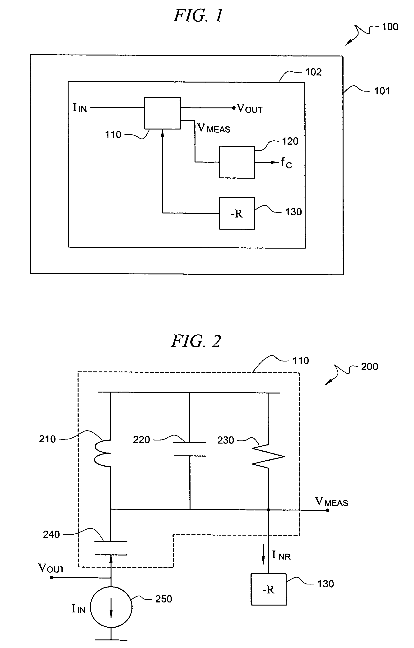
[0019]FIG. 1 is an illustration of exemplary system 100 adapted according to one embodiment of the invention. System 100 includes semiconductor chip 101, upon which is disposed at least part of Radio Frequency (RF) circuit 102. One example of an RF circuit is a tuner for RF signals, though various embodiments are not limited thereto. While circuit 102 is shown disposed entirely upon chip 101, it should be noted that embodiments of the invention are not so limited. Various parts of the tuner may be located off-chip, including, for example, parts of filter 110. For convenience, only a portion of circuit 102 is shown. An example tuner that can be used as an RF circuit in some embodiments is described in U.S. patent application Ser. No. 11 / 441,816, filed May 26, 2006, and entitled “AGC SYSTEMS AND METHODS FOR BROADBAND TUNERS,” the disclosure of which is hereby incorporated herein by reference.

[0020]In this example, filter 110 is an Intermediate Frequency (IF) filter in a signal path of...


PUM


Abstract

A system for implementing a tuner comprising a Radio Frequency (RF) circuit, a filter disposed in a signal path in said RF circuit, a first negative resistance unit in communication with said filter adapted to cancel one or more resistive elements in said filter, a frequency measurement unit in communication with said filter, wherein said first negative resistance unit is adapted to cause said filter to act as an oscillator, and wherein said frequency measurement unit is adapted to measure oscillations of said filter and to calculate a center frequency of said filter therefrom.

Description

CROSS-REFERENCE TO RELATED APPLICATIONS[0001]This application is related to U.S. patent application Ser. No. 11 / 513,521 , filed concurrently herewith, and entitled “SYSTEMS AND METHOD FOR DETECTING CAPACITOR PROCESS VARIATION,” and to U.S. patent application Ser. No. 11 / 513,520, filed concurrently herewith, and entitled “RF FILTER ADJUSTMENT BASED ON LC VARIATION,” the disclosures of which are hereby incorporated herein by reference.TECHNICAL FIELD[0002]This description relates, in general, to RF signal circuits, and, more specifically, to detecting the frequency response of one or more filters in an RF signal circuit.BACKGROUND OF THE INVENTION[0003]Signal tuner circuits include filters that remove one or more frequencies of a signal. Engineers often desire to know the center frequency of a given filter in a tuner circuit in order to determine if the filter itself is defective, should be adjusted, or if other components should be adjusted. This is especially true in semiconductor c...

Claims


Application Information

Patent Timeline
Patent Type & Authority Patents(United States)
IPC IPC(8): H04B1/26
CPCH03H11/1291H03H7/12
Inventor MAGNUSEN, TIMOTHY M.
Owner CSR TECH INC
Why Eureka
Try Eureka